Overhaul
Installation and Service Manual
Adjust the latch release
The latch should release after about 3mm of cable movement. As the brake plates [47] become worn in
the central hole there is less cable movement before the latch releases. Eventually the latch will fail to
lock at all.
If this adjustment is taken too far the latch will either not lock, or will not release. Test the
system thoroughly after adjustment. Test the system in operation in the vessel.
The purpose of this adjustment is to maintain the 3mm of cable movement before latch release.
Screw the nyloc nuts [45] in towards the centre to give more cable travel before release.
Screw the nyloc nuts [45] out from the centre to give less cable travel before release.
Operate the reverse vigorously a number of times to check that the adjustment is stable.
Steering Assembly Overhaul
Refer to drawing: HJ21206000 Steering Assembly.
Remove the Steering Shaft
Remove the reverse duct. Refer to section: Reverse Assembly Overhaul on page 9-6.
Remove the splash guard [58] by removing the two nuts [17] and spring washers [19] securing the splash
guard to the studs [59] fitted to the jet unit tailpipe. Refer to drawing: HJ21207003 Reverse Assembly.
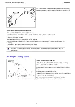
Remove nut [7], spring washer [8] and special washer [6] and remove the cotter [5] retaining the steering
crank [4] to the steering shaft [1]. Note the orientation of the steering crank when fitted to the steering
shaft as this is important for "Nozzle Up", "Nozzle Down".
Push the steering shaft into the vessel, making sure the cotter pin grooves do not to damage the seals
Remove the steering crank [4] from the steering nozzle bush [15].
If the steering shaft is to be removed completely, proceed as follows:
Remove the bolt [36], brake rod bush [33] and flat washers [31] and [32] from the reverse latch brake
rod end [26].
Remove the cable and cable clamp from the cable mount [20] (if the cable is connected as a right hand
drive installation).
Move the latch system out of the way and slide the steering shaft forwards out of the jet unit. Refer to
drawing: HJ21206000 Steering Assembly.
Inspect the flat on the steering shaft where the cotter [5] locates to ensure that the surface is not
damaged. Check that the steering shaft is not bent pitted or excessively worn. Replace the steering shaft
if any damage or excessive wear is evident.
Inspect the condition of the cotter [5] replace if the cotter is worn or damaged.
Check the condition of the crank ball. Replace the crank [4] if the diameter of the ball has worn below
20.8mm (0.82ins) (this should be measured at 90º to the shaft axis).
Inspect the condition of the o-ring seal [2] fitted to the front of the forward steering shaft bush [3].
Replace if worn or damaged.
Check the steering shaft bushes [3] if these are worn or damaged, these should be replaced.
9-12
Содержание HJ212
Страница 1: ...HJ212 Installation and Service Manual R3A3 Jet unit Manual ...
Страница 20: ...Product Description Installation and Service Manual 2 6 ...
Страница 56: ...Commissioning Installation and Service Manual 6 4 ...
Страница 62: ...Fault Finding Installation and Service Manual 7 6 ...
Страница 82: ...Maintenance Installation and Service Manual 8 20 ...
Страница 137: ...Installation and Service Manual Appendix Notes 10 21 ...
Страница 141: ...Installation and Service Manual Appendix Notes 10 25 ...
Страница 164: ...Appendix Installation and Service Manual 10 48 ...
Страница 166: ......
Страница 169: ......
Страница 171: ......
Страница 172: ......
Страница 174: ...5 4 13 5 4 1307 0 3 453 5 4 4 4 05 50 64 8 53 5 50 5 5 3 454 0 8 50 0 5 54 3 5 0 5 8 50 0 5 11307 4 P 4 3 8 5 ...
Страница 175: ......
Страница 176: ......
Страница 177: ......
Страница 178: ......
Страница 181: ......
Страница 185: ......
Страница 186: ......
Страница 188: ......
Страница 195: ......
Страница 196: ......
Страница 197: ...Notes ...


