
P29 Instruction Manual
6
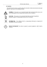
Safety precautions
2.1 Safety concept
When using in systems with natural gas, the entire pressure system must be flooded with the
gas before switching on the electrical power supply. This creates a non-explosive atmosphere
in the gas-carrying system of the unit.
During operation, both pressure ports must be connected to the pressurized system.
The P29 has been subjected to an ignition hazard analysis according to DIN EN 1127-1:2019.
Under normal operating conditions, there is no explosive atmosphere in the transducer.
Consequently, it has no ATEX label, as it does not fall within the sphere of application covered
by Directive RL 2014/34 /EU.
2.2 Appropriate use
The instrument may only be installed outside potentially explosive atmosphere.
The P29 is used to measure differential pressure, volumetric flow, mass flow and flow velocity
using the orifice plate. It may be used in systems with natural gas provided that the
commissioning rules described in Section 3 are observed.
The operator of the device is responsible for supplying a pure (oxygen-free) fuel gas
atmosphere (natural gas). The manufacturer is not liable for damage resulting from
improper or non-intended use.
Always observe the operating requirements
– particularly the permissible supply voltage –
indicated on the rating plate and in the “Technical data” section of this manual.
The instrument may only be handled as indicated in this manual. Modifications to the
instrument are prohibited. The manufacturer is not liable for damages caused by improper use
or failure to follow these instructions. Violations of this type render all warranty claims null and
void.
2.3 Changing to the device
The device may only be handled in accordance with these operating instructions. Modifications
to the device are not permitted. The manufacturer is not liable for damage resulting from
improper or non-intended use. In this case, the warranty claims also expire.
If the device is used improperly or not for its intended purpose, there is a risk of the
device losing its explosion protection effect.
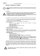
2.4 Shipping, assembly, electrical connections and startup
Assembly and the electrical connections should only be handled by trained professionals. They
should be given proper training and be authorised by the operator of the facility. This applies
particularly to systems that work with natural gas. Special start-up rules (Section 3) apply in
this area.
The following ignition hazards must be taken into account during installation:
“Hot gases”
The gas temperature of the natural gas must be within the permissible
ambient temperatures of the unit. If necessary, ensure sufficient cooling or heating of
the gas or mount the unit in a location where the natural gas has assumed the ambient
temperature of the unit.
Содержание P29
Страница 27: ...P29 Instruction Manual 27 Dimension drawing figure 11 1 dimensional drawing...
Страница 30: ...P29 Instruction Manual 30 Certificate of Conformity NEU_7100 004324_P29 docx 02 2023 Ts...
Страница 31: ...P29 Instruction Manual 31 Notes...
Страница 32: ...P29 Instruction Manual 32 Notes...