


5. Orientation and levelling.
When the main control software is started, or the scanner utility is running, a pitch and roll value will be displayed.
These readouts can be used to help with levelling the LiDAR.
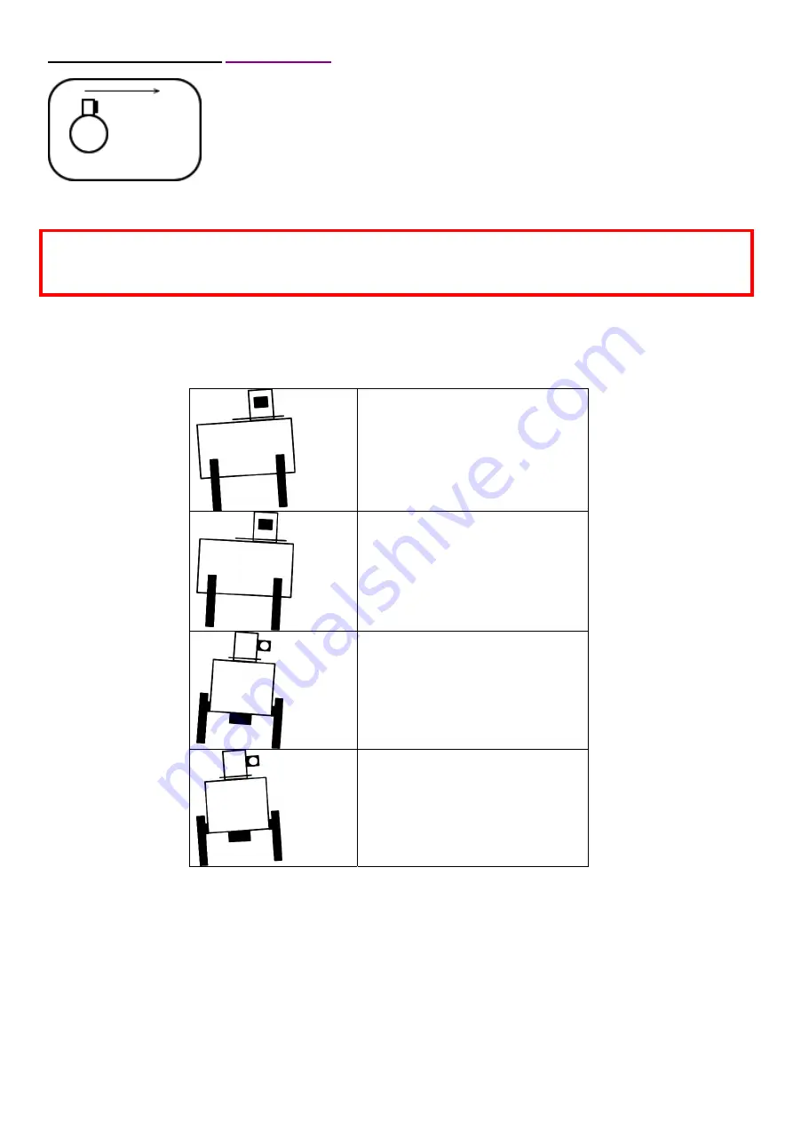
The table below shows each tilt situation, and the corresponding display. The system is shown in its homed.
-ve pitch value will be displayed.
+ve pitch value will be displayed.
-ve roll value will be displayed.
+ve roll value will be displayed.
•
An adjustment knob at the top of each leg will extend and retract a telescopic sub-leg to vary its length. Adjust
the legs in pairs – one end or one side at a time.
•
Turn the adjustment knobs clock wise (looking from above) to retract the leg, and counter-clock wise to
extend.
•
The pitch and roll sensor has a resolution of 0.1 degrees.
Note. For
CSM
scan files, which are defined in motor encoder counts – (not degrees), the offset bearing
will not be
used
, and all movements are with respect to the home position (zero counts). It will be necessary for the scan file
designer to take account of any orientation offset during the scan file creation. For this reason, we would recommend
that the LiDAR be aligned to
face north
in its home position, which will make scan files easier to design.
It is possible to enter a bearing during software setup, which will then be used in
conjunction with all of the azimuth co-ordinates in the scan files. If the LiDAR is
aligned to face north when in its home position (recommended), then a bearing of
0º is used. If it is facing south, then 180º will be used, and the azimuths in the scan
files will be corrected accordingly. The bearing is taken along the direction of the
arrow in the plan view shown. This is the LiDAR’s home position, which the
scanner moves to when the LiDAR powers up.