background image

Getting Started

Gas Connections

IM-Series mass flow controllers/meters do not require straight runs of pipe upstream or 

downstream. 
Devices ship with plastic plugs seated in the processing ports. To decrease the chance of 

contaminating the flow stream, do not remove these plugs until you are ready to install 

the device.
After removing the plugs, immediately connect the device to upstream and downstream 

plumbing, leak-tight. Verify that the flow matches the direction indicated on the device 

body. Standard gas flow controllers/meters have female inlet and outlet ports. Options 

for connections include NPT, SAE, BSPP, and VCR

®

-compatible (some of these fittings may 

have male connections). 

If you are using a fitting that does not have a face seal, use thread-sealing Teflon tape to 

prevent leakage around the port threads, 

but

 do not wrap the first two threads entering 

the device. This will minimize the possibility of tape entering the flow stream and clogging 

the laminar flow elements.
Face seal fittings can be installed without Teflon tape applied to the threads.

∆ 

Caution: 

Pipe dopes or sealants are not recommended on the process connections. 

These compounds can cause permanent damage to the controller should they get into 

the flow stream.

Maximum Pressure

The maximum common mode pressure is 

200 

PSIA

. Common mode pressure is the 

maximum pressure that may be applied simultaneously to both sides of the instrument 

without causing damage.

!


Warning: 

Using the flow controller above the maximum specified common pressure 

will permanently damage the internal pressure sensors. If the line pressure is above 

these limits, use a pressure regulator upstream of the device to reduce the pressure 

below 200 PSIA

.

Maximum Flow

The maximum flow is 25 times the full-scale flow rating of the instrument. Exceeding this 

may cause permanent damage to the internal differential pressure sensor.

Commanding a non-zero setpoint prior to applying the pressure will cause the valve to be 

fully open and will expose the sensor to any instantaneous changes in pressure, such as 

from a snap-acting solenoid valve. For meters and controllers with downstream valves, 

install a flow restriction upstream of the device to limit large, instantaneous changes in 

pressure. 

Power and Signal Connections

Power is supplied to the controller through the DB9 connector on the top of the device. 

The table below indicates how to connect the device to power and communication. If your 

device was built with a different configuration, please refer to the corresponding pinout 

found at 

alicat.com/pinouts

The device power requirement for Factory OEM mass flow devices is: 12–24 VDC, 250 mA 

for the standard device, or 290 mA if equipped with 4–20 mA output. 

!


Warning: 

Do not power the device until all necessary pins have been properly 

connected.

!


Warning: 

Only connect power to pin 7. Connecting power to other pins can permanently 

damage the device.

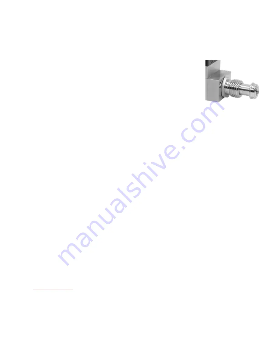
A mass flow controller with male 

VCR®-compatible connections.

Содержание ALICAT IM

Страница 1: ...OPERATING MANUAL FOR MASS FLOW DEVICES Models IM and IMC...

Страница 2: ...a 91 022 41248010 Recalibrate your mass flow controller every year Annual calibration is necessary to ensure the continued accuracy of readings and to extend the Limited Lifetime Warranty Fill out the...

Страница 3: ...tor valve position to maintain your process and identify failures before they occur This manual covers the following instruments IMC Series gas mass flow controllers IM Series gas mass flow meters For...

Страница 4: ...9 Data Format 10 Changing the Setpoint 10 Totalizer 11 Batch Dispensing 11 Changing the Gas 11 Control Loop 11 Command Quick Reference 12 Advanced ASCII Commands 12 Modbus RTU 13 Communicating Via Mo...

Страница 5: ...r overrange etc Mounting The flow controller can be mounted in any position including upside down Mount the device so that flow passes through the flow body in the direction shown by the flow arrow Th...

Страница 6: ...usly to both sides of the instrument without causing damage Warning Using the flow controller above the maximum specified common pressure will permanently damage the internal pressure sensors If the l...

Страница 7: ...s 4 Analog Setpoint Input meters Ground to tare 5 Tx or A Sends RS 232 Tx or RS 485 A signals 6 Analog Signal Output 0 5 Vdc output signal 7 Power in Powers the device 8 Ground Common ground for power...

Страница 8: ...tuning to adjust response speed and stability for some applications Establishing Communication To connect your device to FlowVision 2 0 1 Download FlowVision 2 0 from alicat com flowvision and instal...

Страница 9: ...unit id command unit_id desired_id Taring the Device Taring gives the device a zero reference for flow measurements ensuring that the device provides its most accurate measurements It is recommended t...

Страница 10: ...dable If the device does not receive a valid command it will ignore it If in doubt hit and start again The default streaming interval is 50 ms This can be increased by changing Register 91 while the d...

Страница 11: ...use the reset totalizer command unit_idT Additional Totalizer functions and options are available in the Serial Primer manual alicat com manuals Batch Dispensing For controllers batch dispensing flow...

Страница 12: ...se a different gas unit_idGgas_number Note For more information on our serial communication commands please see the Serial Primer at alicat com manuals Advanced ASCII Commands The command set on IM de...

Страница 13: ...nts are written to 1003 and 1004 The command arguments are variables that influence how the commands modify the device Analog Signals Alternative to the digital communications described above the devi...

Страница 14: ...ranges that start at 0 Vdc a no flow condition is output at approximately 0 010 Vdc The full scale of the device is output by the top of the range 5 Vdc for 0 5 Vdc 10 Vdc for 0 10 Vdc or 20 mA for 4...

Страница 15: ...lessen this sensitivity by increasing the flow averaging Controllers use PD or PD I control loop algorithms to reach the setpoint given These parameters are adjustable in the field Issue My controlle...

Страница 16: ...ility page 2 Serial Communications Issue I can t communicate with the device when it is connected to my PC Action 1 Make sure the baud rate your software and COM port required is the one your flow con...

Страница 17: ...erial has entered your device do not take apart the flow body to clean it as this will negate its NIST traceable calibration Please contact support for cleaning page 2 Recalibration The recommended pe...

Страница 18: ...oxide 5 C2H6 Ethane 6 H2 Hydrogen 7 He Helium 8 N2 Nitrogen 9 N2O Nitrous Oxide 10 Ne Neon 11 O2 Oxygen 12 C3H8 Propane 13 nC4H10 Normal Butane 14 C2H2 Acetylene 15 C2H4 Ethylene Ethene 16 iC4H10 Isob...

Страница 19: ...h Liter per hour US GPM US gallon per minute US GPH US gallon per hour CCS SCCS NCCS Cubic centimeter per second CCM SCCM NCCM Cubic centimeter per minute cm3 h Scm3 h Ncm3 h Cubic centimeter per hour...

Отзывы: