background image


Page 1 


Содержание Quattro Vanguard Original

Страница 1: ...Page 1...

Страница 2: ...Page 2...

Страница 3: ...Page 3...

Страница 4: ...ecification 10 About the Quattro macerator 10 How the Quattro works 11 The pulveriser 11 Technical diagram 12 Specification 13 OLED panel chart 15 Identification of the symbols and indicator lights 15...

Страница 5: ...ternal 34 Lid internal 35 35 Top assembly of cabinet 36 Main pump removal diagram 37 Mechanical assembly removal diagram 38 Mechanical assembly servicing diagram 39 Plumbing diagram 40 Plumbing parts...

Страница 6: ...ent and must be available for use by the owner service engineer as required It must be available during the life of the equipment and passed to any subsequent owner user if the equipment is sold or tr...

Страница 7: ...allation is being used Relevant sections of this manual may be printed from the manual on the CD that accompanies the machine In addition to these general safety instructions you must observe the spec...

Страница 8: ...familiar with the relevant codes of practice or standards which are applicable to the country of installation Preliminary operating advice All instructions located directly on this machine must be ob...

Страница 9: ...studying the manual thoroughly Work on the machine must only be carried out with the machine stopped and electrical power supply turned off at the isolator switch Pumps or assemblies which convey or...

Страница 10: ...can be personalised to each healthcare setting CSA model variants are Foot pedal open manual soft close Hands free open and close automatic Deodoriser disinfectant rinse cycle Night mode RFID Lock Un...

Страница 11: ...rnal microprocessor If a problem occurs cycle termination devices end the cycle of operation and the respective warning or fault light will illuminate For operation refer to the indicator panel This m...

Страница 12: ...Page 12 Technical diagram...

Страница 13: ...ow indicator stub to the drain Ensure any discharge is visible Direction of rotation for macerator motor Single phase machines are supplied with the correct rotation Isolator For single and three phas...

Страница 14: ...e position of the drain in relation to the macerator and the requirements of the hospital this will be agreed during installation Cycle Time seconds Water usage US gallons Water usage Litres Solo dB V...

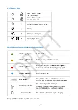
Страница 15: ...t red Machine indicating fault Call for service engineer Please quote fault code when calling see page 48 Indicator light blue Machine in night mode Water filling Rising until the tank is full Illumin...

Страница 16: ...he foot pedal 6 Load the machine MAXIMUM load for this machine Disposable bedpans ONE Urine bottles ONE Wash bowls ONE DO NOT exceed this maximum loading 7 Press the foot pedal to close the lid DO NOT...

Страница 17: ...Page 17 1...

Страница 18: ...ids movement is interrupted and it then reverses to the fully open position if able to do so CAUTION Do not attempt to manually close or open the lid when stationary or during automatic operation this...

Страница 19: ...of 11pm to 4am however the setting could be changed to suit whatever times you think are suitable for you Speak to your facilities estates team if you require this If any further advice is required co...

Страница 20: ...steps 1 Fit the funnel bracket to the left hand side of the machine 2 Secure the bracket by tightening the two thumb screws 3 Place the funnel on the bracket in a tilted position 4 Lower funnel into p...

Страница 21: ...ctions Never allow the pump to run in a dry condition Cold water supply Quattro is designed to operate on a minimum water flow rate of 1 5 US gallons per minute 5 5 litres min The supply into the cist...

Страница 22: ...oduced then the maximum length would reduce to 2 5m Minimum size of waste pipe 50mm Connect the machine to the drain using the minimum number of long radius swept bends Use long radius or swept bends...

Страница 23: ...pipe run is preferable but if necessary any change of direction must be kept to a minimum with an overall length run of two metres However if you need to exceed this length please contact Haigh for f...

Страница 24: ...onal Electrical Code regulations Appropriate National Electrical Code approved cables have been used The appliance is connected to a protective ground connection via the ground terminal and identified...

Страница 25: ...ration Undo the carton lift the lid to periodically rotate the impeller by hand to prevent the mechanical seal seizing Re seal the carton after doing this Industrial gloves must be worn when working o...

Страница 26: ...ess the central fixing down bolt 4 Remove the central fixing down bolt Floor Bracket Fastener Details Type hexagonal Head 13 A F Size M8 x 20mm 5 Replace the control box and remove the machine from th...

Страница 27: ...derneath until the floor locating bracket locates in the two guide slots in the runners 6 Secure the machine and connect services Replace the mounting base bolt under the motor to secure the machine i...

Страница 28: ...s been securely bolted down Clean off any accumulated surface dust and dirt Check inside the machine and surrounding area for tools fasteners rubbish or other foreign objects and remove them according...

Страница 29: ...orrectly Check that the drain block pressure switch tube is clear of water Check and clean solenoid filter or replace Mechanical Check wear on the hopper cutter ring impeller Check that the impeller i...

Страница 30: ...ith the same cleaning solution Lubrication The machine is designed for minimum maintenance The clip bushes used in this machine must not be lubricated Apply anti seize compound if indicated The motor...

Страница 31: ...carried out by a qualified person Ensure appropriate protective equipment is worn ALWAYS isolate the machine from mains electrical supply before servicing Isolate the water inlet to the pump at the se...

Страница 32: ...Page 32 General assembly...

Страница 33: ...tting 1 9 901 114356 Frame Top Plate Assembly 1 10 906 111694 Inlet Plumbing Assembly 1 11 907 110942 Drain Outlet Assembly 1 12 902 111567 Pulveriser Head Assembly 1 13 901 113409 Foot Pedal Assembly...

Страница 34: ...793 Lid Closed Microswitch Assembly Vanguard Enhanced Only 1 4 901 111587 Lid Seal Assembly 1 5 901 107162 Screw 6 6 901 111600 Striker Assembly 1 7 901 111421 Striker Seal included with Striker Assem...

Страница 35: ...Assembly 1 4 901 111547 Latch Packer 1 5 901 114341 Lid Plate 1 6 901 111587 Lid Seal Assembly 1 7 900 013486 Spray Vent 1 8 900 013522 Screw M5x16 SCKT CSK HD 1 9 901 111288 Spray Inlet 1 10 902 111...

Страница 36: ...Page 36 Top assembly of cabinet Item Part number Description Qty 1 902 110877 Cabinet Top 1 2 901 111006 Hopper Top Seal 1...

Страница 37: ...Page 37 Main pump removal diagram 3...

Страница 38: ...Page 38 Mechanical assembly removal diagram 3 4 5 6...

Страница 39: ...bly 1 6 901 111266 Motor Hinge Plate 1 7 910 014614 Motor 120V 1 60Hz 1 8 901 111578 Speed Sensor 1 9 901 013924 Water Thrower 1 10 901 114580 Anti vibration pad 2 11 901 111568 Sealed Screw 4 12 728...

Страница 40: ...Page 40 Plumbing diagram...

Страница 41: ...1 902 013945 10mm x 8mm Reducer 1 12 902 111626 HPR Solenoid Assembly 1 13 901 110425 Manifold 1 14 901 013727 Stem Elbow 8 x 8 1 15 902 108636 Reducing Elbow 8 6 1 16 632 000139 Tube 6 x 4 JG LLDFE 2...

Страница 42: ...02 030154 A7 Overload Device 4 0 6 2A 1 4 106 031088 A5 Relay 1 5 100 031012 Grey Terminal 1 6 130 031012 End Cover 1 7 127 031012 Fused Terminal 15A 1 8 113 031099 A3 Fuse 12A HBC 20mm x 5mm Dia 1 9...

Страница 43: ...Page 43 Wiring diagram single phase 1 PHASE MOTOR 120 VOLTS 1 PHASE PUMP MOTOR 120 VOLTS...

Страница 44: ...afety Monitoring n a Unlatched Micro switch Safety Monitoring 902 107552 Lid Release Solenoid Lid Release 901 113188 Lid Opening Motor Lid Open Close n a Hinge Fully Open Micro switch Lid Open n a Hin...

Страница 45: ...ve the vent clean it and replace it The jet gap must be the same around its circumference If the problem is with the pump you will require an exchange unit for this part Lid seal is leaking Check that...

Страница 46: ...water leakage The pulveriser or pump mechanical seal is leaking Fit a new mechanical seal in the main assembly or if the pump is leaking exchange this for a new part The plumbing is leaking Investigat...

Страница 47: ...n in line valves not operating correctly Clean or replace as required Never use a reactive chemical drain block clearer within the machine as it will damage the seals F7 Cistern fails to replenish wit...

Страница 48: ...tuator Current monitoring an object has been detected that would interfere with the lid closing F13 Logged Only Latch Actuator Current monitoring an object has been detected that would interfere with...

Страница 49: ...Page 49...

Отзывы:

Похожие инструкции для Quattro Vanguard Original