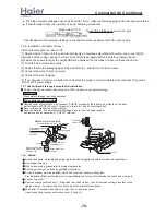
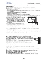
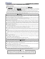
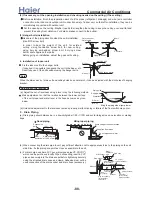

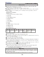

Place where it is easy to route drainage pipe
and outdoor piping.
Place ,away from heat source and with less
direct sunlight.
Place where cool and warm air could be
delivered evently to every corner of the room.
Place near power supply socket.Leave enough
space around the unit.
Place ,robust not causing vibration,where the
body can be supported sufficiently.
To prevent interference, place it at least 1m
away from other electric machines, such as
TV set, radio.
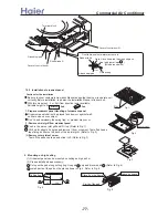
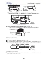
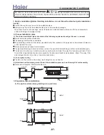
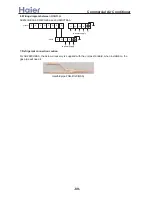
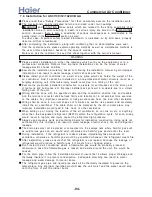
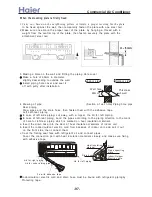
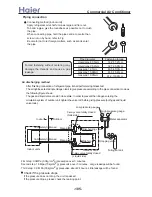
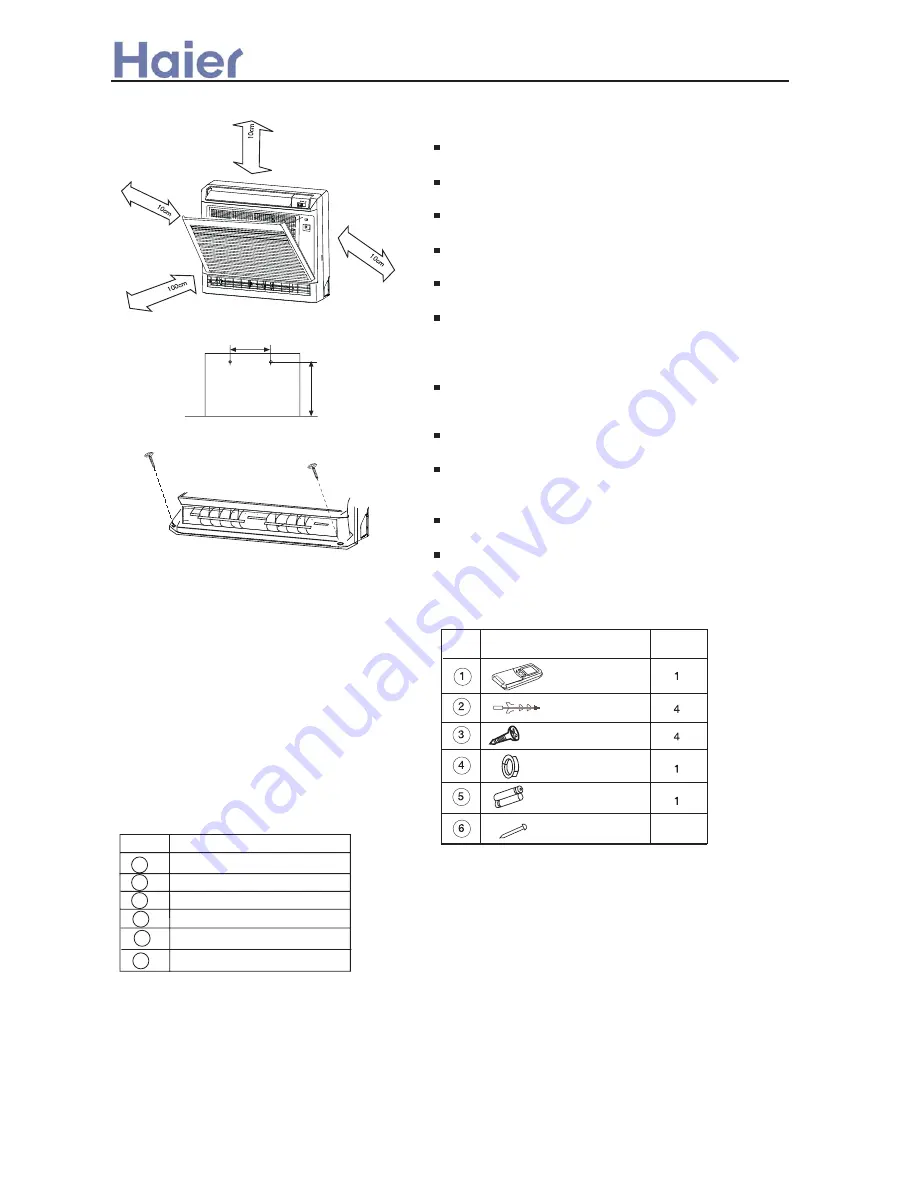
Installing
According to the dimension of the figure 2 shown,
nail two cement steel nails on the wall,Keep 2~3
mm out.then hang the back of the unit on them.
There must be no gap between the indoor unit
and wall.
Remove the front panel,then use two expansible
screws to fix the unit on the floor.As figure 3
shown.
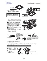
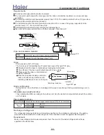
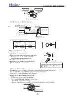
Once refrigerant piping and drain piping connections
are complete,fill the gap of the throght hole with putty.
Attach the front panel and front grille in their orginal
positions once all connections are complete.
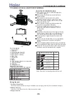
Tool necessary
1. Screw driver
2. Hacksaw
3. 70mm dia.hole core drill
4. Spanner(dia. 17,27mm)
5. Spanner(14,17,27mm)
6. Pipe cutter
7. Flaring tool
8. Knife
9. Nipper
10. Gas leakage detector or soap water
11. Measuring tape
12. Reamer
13. Refrigerant oil
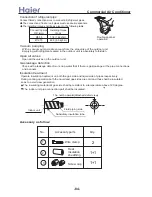
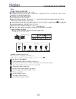
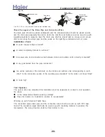
Standard accessories
Following parts shall be field supplied
Note: There isn't connecting wire with this unit.
No.
Shape and description
QTY
Remote controller
Self-tapping screw
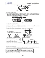
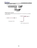
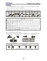
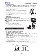
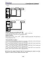
1. Position of the wall hole
Wall hole should be decided according to installation place and piping direction.(refer to installation drawings).
2. Making a wall hole
Drill a hole of 120X70mm dia. with a little slope towards outside.
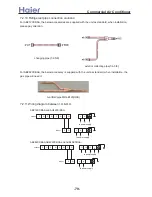
3. Piping connection
Dry battery #7
Wall hole cover
Cement steel nail
6
7.5 Installation of indoor unit (AF07/09/12/142XCBAA)
Selection of installation place
Fig1
Mark
Part name
Adhensive tape
Pipe clip
Connecting hose
Insulation material
Putty
Drain hose
A
B
C
D
E
F
330
617
Fig2
Fig3
more than
more than
more than
more than
Expansion bushing
Fixing the unit
>a__WcU[S^ <[c >a`V[e[a`Wc
-90-
Содержание AB072XCBAA
Страница 21: ... a__WcU S c a V e a Wc AU84NXTBAA 66 33 1 23 4 43 33 61 2 3 160 2 15 3 52 21 ...
Страница 28: ... a__WcU S c a V e a Wc w y z x wt9 61 xt 98 96 816 yt5861 zt256 1 o MRWMHI p t9 61 2v xB r 2v xB r 2wzxB 28 ...
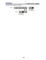
Страница 138: ... a__WcU S c a V e a Wc AU282XHBAA AU422XIBAA PCB printed diagram 138 ...
Страница 141: ... a__WcU S c a V e a Wc AU84NXTBAA PCB printed diagram 141 ...
Страница 144: ... a__WcU S c a V e a Wc AB AE AD units PCB printed diagram 144 ...
Страница 149: ... a__WcU S c a V e a Wc AF07 142XCBAA PCB printed diagram 149 ...
Страница 180: ...MEMO Commercial Air Conditioner ...