
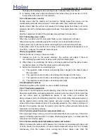

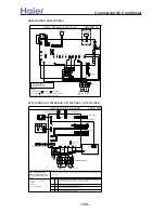
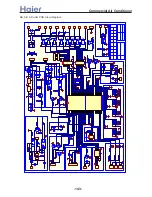
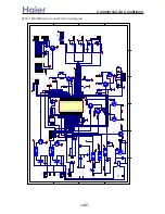

AD282XHBAA, AD422XHBAA:
POWER
SUPPLY
TO
OUTDOOR
UNIT
2
1
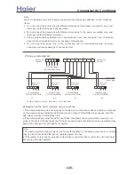
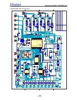
1. Central controller and fresh air are optional.
2. Dashed part is fan motor speed controller module
3. P16 and P17 are used for room card function
3
P17
SW3
(H)
(M
)
(CO
M
M
)
(L)
(N')
(H
UM
I)
(HE
A
T
)
(P
UM
P)
T3
.1
5A/2
50VAC
W
Y:Yellow OR:Orange
R:Red Y/G:Yellow/Green
BL:Blue BR:Brown
W:White B:Black
NOTE:
B
W
P2(N)
P1(L)
P6(N4)
W
ROOM
SENSOR
B
FC
SENSOR
TEMP.
3
4
L
N
1 2
P Q
FAN MOTOR
Y/G
M
B
FAN CAP.
W
W
Y/G
B
(ROOM/PIPE)
7
7
8
8
8
7
3
1
3
4
3
NO
NC
4
NC
NO
2
1
2
1
3
NC
NO
4
2
5
6 COM
5
6
5
COM
6 COM
R
B
BL
CN10
CN6
PIPING TEMP.
SW2
1
ON
4
2
1
ON
23
SW1
23
4
1
ON
WIRED
CONTROLLER
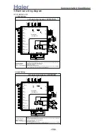
CIRCUIT DIAGRAM OF INDOOR UNIT
P10
FU
SE
P4(N2)
P3(N1)
CN7
(F
RE
SH
)
P8
P7
P9
2
CN5
CON
T
ROLL
E
R
)
(A
L
A
R
M
)
CN12
(REMOTE)
CN16
P16
P13
P12
P11
P14
P15
(L')
A
1
(F
L
O
A
T
)
22
1
ON
SW5
34
CN21
4
3
1
ON
SW4
SWITCH
FLOAT
B
(D
O
O
R
)
CN11
CN15
0010575122
REMOTE
CONTROLLER
CENTRALIZED
(O
XYG
EN
)
(S
WIN
G
)
CN1
TRANS.
CN4
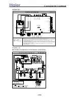
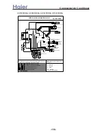
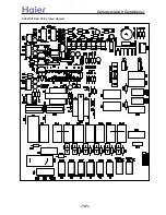
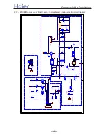
AF072XCBAA, AF092XCBAA, AF122XCBAA, AF142XCBAA:
NOTE: PARTS IN DASH FRAME ARE OPTIONAL.
REMOTE CONTROL DETECTOR
SW1 is a emergency key.
SW2 is used to choose the
working satate of douwn PG
motor.
BOTTOM LOUVER MOTOR
RECEIVING BOARD
OPTIONAL BOARD
Y/G: YELLOW/GREEN
B : BLACK
BL : BLUE
W : WHITE
R : RED
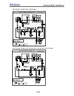
If the controller power on, the indoor unit run according to the state on the controller;
Ignore the state on the controller and power off
The controller is able to be controlled
Ignore the state on the controller and power off
If the controller power off, the indoor unit run in the auto mode
0
1
0
1
0
0
1
1
Connect To Outdoor Unit
Working state of the wire controller
SW3 and SW4 are used to choose the working state of the wire controller. The detailed information see
TERMINAL BLOCK
To Power Supply
(1PH,220-230V~,50Hz)
SW3 SW4
CN1
T 3.15A/250V~
CN22
CN8
CN2
CN4
CN3
CN28
CN7
CN27
CN5
FUSE
POWER SUPPLY BOARD
CN103
CN101
TOP LOUVER MOTOR
INDOOR WIRING DIAGRAM
CN26
CN20
CN21
CN15
PIPING TEMP. SENS0R
TOP FAN MOTOR
BOTTOM FAN MOTOR
0010573507
AMBIENT TEMP. SENSOR
the following:
>a__WcU[S^ <[c >a`V[e[a`Wc
-135-
Содержание AB072XCBAA
Страница 21: ... a__WcU S c a V e a Wc AU84NXTBAA 66 33 1 23 4 43 33 61 2 3 160 2 15 3 52 21 ...
Страница 28: ... a__WcU S c a V e a Wc w y z x wt9 61 xt 98 96 816 yt5861 zt256 1 o MRWMHI p t9 61 2v xB r 2v xB r 2wzxB 28 ...
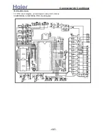
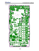
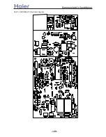
Страница 138: ... a__WcU S c a V e a Wc AU282XHBAA AU422XIBAA PCB printed diagram 138 ...
Страница 141: ... a__WcU S c a V e a Wc AU84NXTBAA PCB printed diagram 141 ...
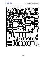
Страница 144: ... a__WcU S c a V e a Wc AB AE AD units PCB printed diagram 144 ...
Страница 149: ... a__WcU S c a V e a Wc AF07 142XCBAA PCB printed diagram 149 ...
Страница 180: ...MEMO Commercial Air Conditioner ...