
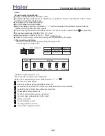
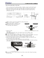
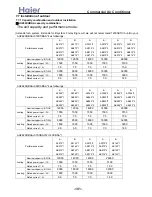

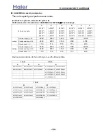
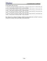
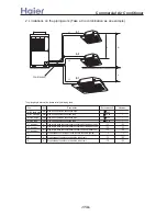
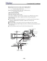
97.2-118.6N.m
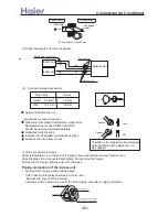
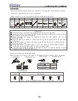
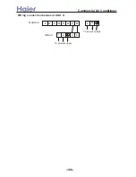
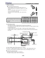
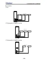
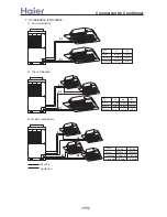
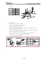
Connecting method (indoor unit)
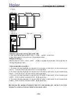
Apply refrigerant oil at half union as large and flare nut.
To bend a pipe, give the roundness as possible not to crush
the pipe.
When connecting pipe, hold the pipe centre to centre then
screw nut on by hand, refer to Fig.
Be careful not to let foreign matters, such as sands enter
the pipe.
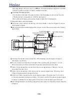
Piping connection
Forced fastening without centering may
damage the threads and cause a gas
leakage.
Pipe diameter
Fastening torque
Liquid pipe 6.35mm
Gas pipe 15.88mm
Liquid pipe 9.52mm
Gas pipe 19.05mm
14.2-17.2N.m
61.8-75.4N.m
32.7-39.9N.m
Gas pipe 12.7mm
49.5-60.3N.m
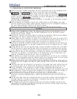
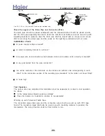
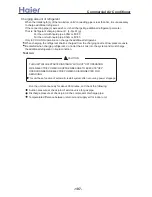
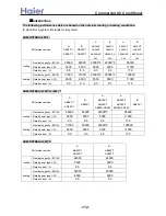
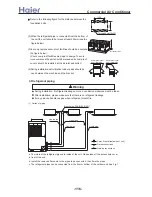
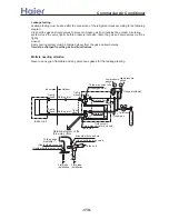
First step: 0.3MPa (3.0kg/cm2g) pressurize over 3 minutes.
Second step: 1.5Mpa (15kg/cm2g) pressurize over 3 minutes. Large leakage will be found.
Third step: 3.0 MPa (30kg/cm2g) pressurize about 24 hours. Little leakage will be found.
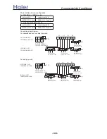
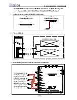
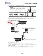
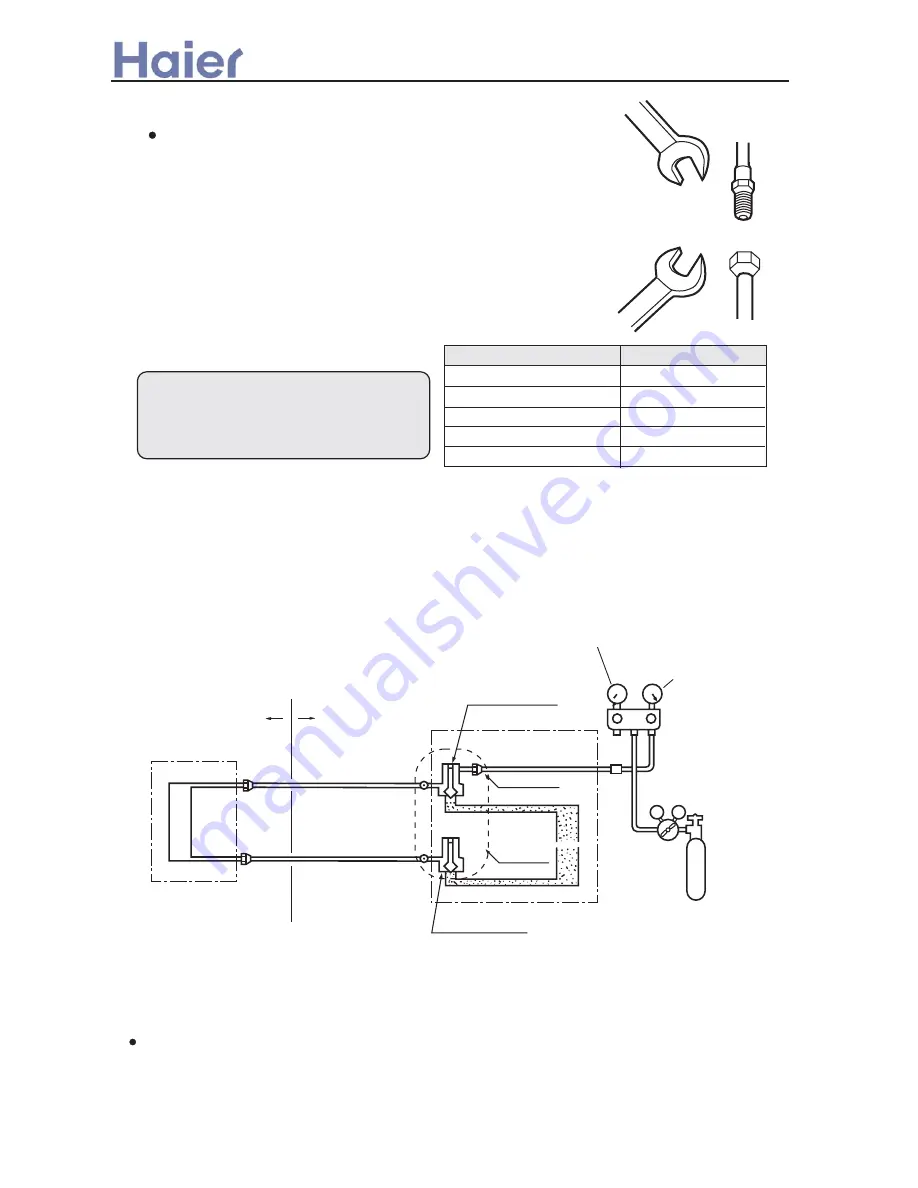
After finishing connection of refrigerant pipe, it shall perform air tightness test.
The air tightness test adopts nitrogen tank to give pressure according to the pipe connection mode as
the following figure shown.
The gas and liquid valve are all in close state. In order to prevent the nitrogen entering the
circulation system of outdoor unit, tighten the valve rod before giving pressure (both gas and liquid
valve rods).
Outdoor
Completely tightened
Completely tightened
Flare part
Outdoor units
Mainhole
Discharging valve
3-way valve totally closed
(Gas side)
Low pressure gauge
High pressure gauge
Meter separator
Dropping valve
2-way valve totally closed
(Liquid side)
Nitrogen tank
VLVH
Indoor units
Indoor
Flare part
Air discharging method
Check if the pressure drops
If the pressure does not drop, the unit is passed
If the pressure drops, please check the leaking point.
>a__WcU[S^ <[c >a`V[e[a`Wc
-105-
Содержание AB072XCBAA
Страница 21: ... a__WcU S c a V e a Wc AU84NXTBAA 66 33 1 23 4 43 33 61 2 3 160 2 15 3 52 21 ...
Страница 28: ... a__WcU S c a V e a Wc w y z x wt9 61 xt 98 96 816 yt5861 zt256 1 o MRWMHI p t9 61 2v xB r 2v xB r 2wzxB 28 ...
Страница 138: ... a__WcU S c a V e a Wc AU282XHBAA AU422XIBAA PCB printed diagram 138 ...
Страница 141: ... a__WcU S c a V e a Wc AU84NXTBAA PCB printed diagram 141 ...
Страница 144: ... a__WcU S c a V e a Wc AB AE AD units PCB printed diagram 144 ...
Страница 149: ... a__WcU S c a V e a Wc AF07 142XCBAA PCB printed diagram 149 ...
Страница 180: ...MEMO Commercial Air Conditioner ...