background image

Page 14

LCD CONSOLE HOOKUP

1.


4 LCD Consoles (Models 11A00-1, 11A00-2, 11A00-9, and 15A00) MAXIMUM per system, subject to power availability.

2.


Use 4-conductor 22-gage wire, 1000 feet maximum length.  Consoles can be homerun or daisy chained. This length shall be
divided by the total number of consoles at the end of the run.  For example, for 4 consoles, the maximum length reduces to
250 feet.  All LCD Consoles are connected to the same 4 wires, RED (+12), BLK (Ground), YEL (A), GRN (B).

3.


The console should be mounted so that the LCD display is at or slightly above eye level.  Consoles should be kept out of the
reach of young children.  A good height is approximately 58 inches from the floor to the bottom of the console enclosure.

4.


Remove console face from back plate (slots on bottom of console will release back plate, use a screwdriver).  Mount the back
plate to the wall.  Mounting holes are designed to fit on a single or double gang box, or directly to the wall.  Pull the wires
from the wall through the opening in the back plate.  Splice the wires to the supplied cable.  Connect the cable to the
connector on the console board (J1).  Snap the console face on to the back plate.  Remove protective film from the LCD lens.

5.


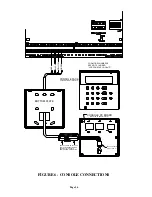
Refer to 

FIGURE 6 (CONSOLE CONNECTIONS)

 for this configuration.

CONSOLE SETUP

The console has different operating options that can be setup from the console to the user's preference.  If more than one console
is being used, it is required that you give each console a different address.  You can change the address of a console through the
console setup mode.

To enter the console setup mode, simultaneously press and hold the 4 and up arrow (

!

) for approximately 1 second.  The console

will beep 5 times and enter the setup mode.  The top line of the display will indicate what you are doing, followed by the current
setting.  The bottom line will show a menu of your options.  To the lower right corner of the display is the direction arrow(s).
Where possible, the up (

), down (

), and two-headed (

) arrow characters are shown on the console display to indicate which

arrow keys may be pressed at that time.  Press the down arrow (

"

) key to advance to the next item.  Press the up arrow (

!

) key to

go back to the previous item.

CONSOLE ADDRESS

If you are installing more than one console, each console must be set to a different address.  The default address setting is (1) -
this is adequate if only one console is being used.  The choices at the bottom are 1-16; however, the OmniLT only supports 4
consoles. When making your choice, choose an address between 1-4, then press the # (pound) key.

SOUNDER

If you wish not to hear the beeper in the console for any reason, the sounder option can be turned off.  Select (0) for OFF or (1)
for ON, then press the # key.

KEY CLICK

The sounder makes a click every time a key is pressed.  This option may also be turned off.  Select (0) for OFF or (1) for ON,
then press the # key.

KEY BACKLIGHT

The keys on the console keypad are lit.  The keys can be never lit, always lit, or only lit when the LCD display is lit.  Select (0)
OFF, (1) for ON, or (2) TIMED, then press the # key.

VIEWING ADJUSTMENT

This option is an adjustment for the viewing angle of the LCD display.  This has been set to its best value at the factory, however,
you may wish to tweak it.  The display has 20 levels of adjustment.  Select (1) for a lower viewing angle, or (2) for a higher
viewing angle.

Содержание OmniLT Automation

Страница 1: ...Installation Manual Document Number 21I00 1 Rev A October 2000 ...

Страница 2: ...Document Number 21I00 1 Rev A October 2000 Copyright v v v v 2000 HAI All Rights Reserved www homeauto com ...

Страница 3: ...4 2 FORMAT 29 3 1 FORMAT 30 OPENING AND CLOSING REPORTS 30 INSTALLER SETUP 31 SETUP CONTROL 31 X 10 HOUSE CODE 31 X 10 3 PHASE 31 OUTPUT TYPES 31 SETUP ZONES 32 WIRELESS RECEIVER 32 ZONE RESISTORS 32 ZONE RESPONSE TIME 33 ZONE TYPES 33 LATCHING ZONE TYPES 33 DESCRIPTION OF ZONE TYPES 33 SETUP DIGITAL COMMUNICATOR 36 FIRST PHONE NUMBER FIRST ACCOUNT NUMBER 36 SECOND PHONE NUMBER SECOND ACCOUNT NUMB...

Страница 4: ... 8 FIGURE 3 TWO WIRE FIRE ZONE CONNECTIONS 10 FIGURE 4 FOUR WIRE FIRE ZONE CONNECTIONS 11 FIGURE 5 RJ31X JACK CONNECTIONS 13 FIGURE 6 CONSOLE CONNECTIONS 16 FIGURE 7 BELL CONNECTIONS 17 FIGURE 8 REMOTE KEYSWITCH CONNECTIONS 19 FIGURE 9 HAI THERMOSTAT CONNECTIONS 20 FIGURE 10 PESM CONNECTIONS 23 FIGURE 11 RS 232 CONNECTIONS 24 FIGURE 12 RS 485 CONNECTIONS 24 ...

Страница 5: ...OOKUP 1 When choosing a place to mount the controller consider the following a A duplex outlet preferably on its own circuit is required to be within 5 feet of the controller for the power transformer and the X 10 Interface Module if used b The controller should be protected from weather temperature extremes and burglars 2 GROUND THE CONTROLLER GND TERMINAL TO A COLD WATER PIPE OR TO A 4 FOOT GROU...

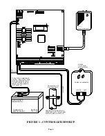
Страница 6: ...E IN ACCORDANCE WITH THE NATIONAL ELECTRIC CODE ANSI NFPA 70 14 GA WIRE POWER TRANSFORMER 16 5 VAC 40 VA REVERE P N RT 1640SL OR EQUIVALENT YUASA NP7 12 OR EQUIVALENT 1 4 SPACING THE BATTERY IS NON POWER LIMITED THE BATTERY LEADS MUST BE SEPERATED FROM ALL OTHER POWER LIMITED WIRING IN THE ENCLOSURE BY AT LEAST 1 4 FIGURE 1 CONTROLLER HOOKUP ...

Страница 7: ...50 ohms The default setting for ZONE RESISTORS is Yes The default settings for all zone inputs on an OmniLT controller are configured as Auxiliary inputs BURGLAR ZONE HOOKUPS The OmniLT system supports both normally open and normally closed switches Most contacts designed for doors windows motion detectors glassbreak detectors and other security devices meet this requirement An external 1000 ohm e...

Страница 8: ...RE ZONE EOL COM OUT2 SWITCH 12V WARNING DE ENERGIZE THIS FROM ELECTRIC SHOCK TO PREVENT RISK NO SMOKE ZN 12V 4 WIRE ZN 1K 12V SMK NRM J9 2 WIRE FIRE ZONE Z8 ZONE ZN SMOKE 2 WIRE 12V NRM SMK J9 AUXILIARY 12V CONSOLE AND OUTPUTS ARE INCLUDED IN THE TOTAL DEVICE LOAD WHICH CANNOT EXCEED 0 5 AMP SOUNDERS CANNOT EXCEED 1 AMP IN UL INSTALLATIONS SOUNDERS CANNOT EXCEED 350mA NOTES 3 2 OUTPUT EOL 1K OUTPU...

Страница 9: ...o Zone 8 1 Use normally open closed for alarm two wire SYSTEM type smoke detectors System Sensor 2100TS or equivalent rated 8 14 VDC 2 Smoke detectors must be connected to Zone 8 and configured as a Supervised Fire Zone 3 An external 1000 ohm end of line resistor must be used 4 Connect to the SWITCHED POWER OUTPUT as shown 5 The Zone 8 Jumper J9 must be in the SMK smoke position 4 Refer to FIGURE ...

Страница 10: ...OM BOTTOM SYSTEM SENSOR MODEL 2100TS MODEL 2100TS SYSTEM SENSOR WHEN Z8 USED FOR SMOKE J9 MUST BE IN THIS POSITION BE CONFIGURED AS A SWITCHED OUTPUT THIS OUTPUT MUST 1K OHM EOL RESISTOR HAI MODEL 1503A0011 FIGURE 3 TWO WIRE FIRE ZONE CONNECTIONS ...

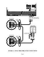
Страница 11: ...YELLOW BLACK GREEN RED HAI MODEL 1503A0011 1K OHM EOL RESISTOR BLACK GREEN RED WHEN Z8 USED FOR SMOKE J9 MUST BE IN THIS POSITION SYSTEM SENSOR MODEL 2112 24TR SYSTEM SENSOR MODEL 2112 24TR THIS OUTPUT MUST A SWITCHED OUTPUT BE CONFIGURED AS SYSTEM SENSOR YELLOW GREEN RED BLACK YELLOW YELLOW GREEN RED BLACK FIGURE 4 FOUR WIRE FIRE ZONE CONNECTIONS ...

Страница 12: ... WIRE IS MISSING HAVE THE CUSTOMER INSIST THAT THE TELEPHONE COMPANY INSTALL ONE FOR THE SAFETY OF THE CUSTOMER 6 WHEN WIRING A RJ31X JACK MAKE SURE THAT THE INCOMING PHONE LINES GO TO THE TELEPHONE COMPANY SURGE ARRESTOR BEFORE THEY GO TO THE RJ31X JACK 7 When the RJ31X is installed as shown locate the green red brown and gray wires from the 8 conductor phone cable and connect to the section on t...

Страница 13: ...SURE TIGHT FIT GREEN RED RED GREEN RJ11 HOUSE PHONE JACK S TO ALL HOUSE TELEPHONES KSU AND COMPUTERS TO TELCO INTERFACE AT SURGE ARRESTOR SURGE ARRESTOR MUST BE GROUNDED TELEPHONE NETWORK INTERFACE SURGE ARRESTOR CUSTOMER ACCESS FIGURE 5 RJ31X JACK CONNECTIONS ...

Страница 14: ...enter the console setup mode simultaneously press and hold the 4 and up arrow for approximately 1 second The console will beep 5 times and enter the setup mode The top line of the display will indicate what you are doing followed by the current setting The bottom line will show a menu of your options To the lower right corner of the display is the direction arrow s Where possible the up down and t...

Страница 15: ...e LCD backlight and the keypad key will be lit and the LCD will display NO CONTROLLER DATA 2 Simultaneously press and hold the 7 and the down arrow keys for approximately 3 seconds The beeper will beep 5 times the LCD backlight and keypad backlight will turn off and the display will clear The LED at the top right corner of the console will start to cycle through its different colors red green yell...

Страница 16: ...CABLE TO CORRESPONDING ENDS OF 4 WIRE CABLE COMING FROM CONTROLLER BOTTOM PLATE CONSOLE FACE SNAPS ON TO BOTTOM PLATE CONSOLE PC BOARD MOUNTED TO CONSOLE FACE RED BLACK YELLOW GREEN FOR MODEL NUMBERS SEE NOTE 1 UNDER LCD CONSOLE HOOKUP FIGURE 6 CONSOLE CONNECTIONS ...

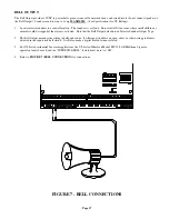
Страница 17: ... if the alarm is activated Note that the Bell Output defaults to an Interior Sounder Output Type 2 The Bell Output monitors the wiring to bells and sirens It will report trouble if an open short or other wiring problem is detected in the supervised bell circuit It will also make a digital dial out when violated 3 For UL Listed residential fire alarm applications the UL Listed Wheelock Model MT 12 ...

Страница 18: ...ered by 12 VDC has 12 VDC triggered inputs and has 2 or more channels The Communicator outputs are activated 3 seconds before the OmniLT dialer begins to dial either using its built in digital dialer or voice dialer The following events will activate the BURG output Burglar alarms including panic zones Auxiliary emergencies Police emergencies and Duress alarms Fire alarms and the fire emergencies ...

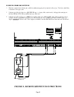
Страница 19: ...een OFF and AWAY Entry and Exit delays are still active 3 Configure one of the outputs as an ARMED and another output as an OK TO ARM output These outputs are used to activate a red and a green LED based on the state of the alarm system The ARMED and OK TO ARM outputs can supply a maximum of 100 mA each These outputs are included in the total DEVICES load which cannot exceed 500 mA MOMENTARY CONTA...

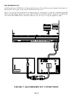
Страница 20: ...d hold and other items Run a 3 or 4 conductor wire from OmniLT to the thermostat location All thermostats are connected to the GRN Green BLK Black and YEL Yellow terminals in the section marked TSTAT on the OmniLT controller Connect the red COMM cable wire with the black COMM cable wire Make the connections as shown in Figure 9 using the supplied wire splices FIGURE 9 HAI THERMOSTAT CONNECTIONS ...

Страница 21: ...e HVAC system When the automation system is in setback mode and the actual temperature is between the LO and HI setpoints the relay energizes to break the 24V red wire hence the HVAC system will no longer operate In heating season when the actual temperature falls below the LOW setpoint the automation system turns the relay in the PESM off thus restoring power to the thermostat allowing the thermo...

Страница 22: ...umps take a longer time to recover from setback so it may be advantageous to program a setback only for extended periods such as a vacation OUTDOOR TEMPERATURE TEMPERATURE SENSORS The Model 14A00 is a temperature sensor that can mount in an outdoor location usually under an overhang and sends the outdoor temperature to an OmniLT system It is coated with a sealant to withstand outdoor moisture The ...

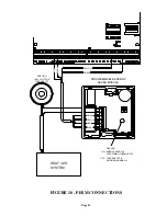
Страница 23: ...M BLACK RED YELLOW GREEN PROGRAMMABLE ENERGY SAVER MODULE RED LED ON ENERGY SAVER IS OVERRIDING THERMOSTAT OFF THERMOSTAT IS WORKING NORMALLY YELLOW GREEN BLACK RED EXISTING LOW VOLTAGE THERMOSTAT FIGURE 10 PESM CONNECTIONS ...

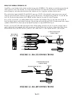
Страница 24: ...use the HAI Model 21A05 2 OmniLT Serial Cable Kit Plug one end of the cable into the J5 Serial modular connector on the OmniLT controller Plug the other end into the Model 21A05 1 Communication Cable Adaptor modular to DB 9 RS 232 which connects the OmniLT serial port to computer DB 9 RS 232 port To make you own serial cable follow the diagrams below When making connections be sure to correctly or...

Страница 25: ...e if the alarm is tripped If the consoles are not operating properly make sure that consoles do not have the same address and check the wiring 2 With all doors and windows closed and all motion detectors normal the bottom line of the display should read SYSTEM OK If there are any trouble indications that occurred during installation press to acknowledge them and silence the beeper 3 Set the time a...

Страница 26: ... siren Be sure that no one is standing near a siren Activate the alarm and ensure that the siren is activated FIRE ZONE CHECK OUT 1 Press to return the console to the SYSTEM OK indication Check the fire zone per the sensor manufacturer s instructions The fire alarm should be activated three pulse temporal pattern 2 Press to silence the alarm The display will still indicate that the FIRE ZONE is NO...

Страница 27: ...he STATUS light is still not blinking check the AUX 12V with a DC voltmeter It should be 13 7 volts If not make sure that there isn t too much load on the system Disconnect all loads If the STATUS LED still won t blink there is a problem with the controller board and it must be returned to HAI for repair Phone line problems or problems with the OmniLT voice are usually the result of the RJ31X jack...

Страница 28: ...he key to success with three way wall switches is to identify the wire that was connected to the COMMON terminal of the old manual switches and to following the instructions precisely 4 Modules that work intermittently from the OmniLT but reliably locally usually have a problem hearing the X 10 signal over the power lines Some tips Make sure connections to the modules and to the TW523 interface ar...

Страница 29: ...nt such as a security zone no longer tripped Trouble conditions are reported as well as restoration of these trouble conditions For security armings and disarmings this event qualifier is also used to identify whether the report is for an arm or disarm The reporting format for Contact ID is listed in Appendix A in this manual When using Contact ID the alarm codes and or reporting format cannot be ...

Страница 30: ... the central station The code that is sent is defined as OTHER OPEN If the system is armed by any other method other than one that requires a code i e Quick Arm Keyswitch or Scheduled Program the communicator will send a generic CLOSE report to the central station The code that is sent is defined as OTHER CLOSE DEFAULT REPORTING CODES FOR 4 2 FORMAT CODE ZONE CODE ZONE 98 TEST CODE 81 FREEZE ALARM...

Страница 31: ...R SETUP MENU 1 CTRL 2 ZONE 3 DCM 5 TEMP 6 MISC 7 EXP SETUP CONTROL To setup the X 10 and Outputs from the Installer Setup menu select the 1 CTRL key The X 10 house code must be specified as well as the output type for each of the Outputs The output type for the Bell output may also be changed Press to advance to the next item to go back X 10 HOUSE CODE The X 10 House Code is the house code for uni...

Страница 32: ...S To setup the zone type for each security zone from the Installer Setup menu select the 2 ZONE key WIRELESS RECEIVER A Wireless Receiver can be used to add 16 zones 9 24 to the OmniLT If used you must enable the following item WIRELESS RECEIVER 0 0 NO 1 YES NOTES 1 If the Model 22A00 Expansion Module is used if must be configured under Setup Installer Expansion 2 If a Wireless Receiver is used an...

Страница 33: ...4 Freeze WATER 55 Water FIRE TAMPER 56 Fire Tamper AUXILIARY 64 Auxiliary KEY SWITCH 65 Keyswitch Input ENERGY SAVER 80 Programmable Energy Saver Module OUTDOOR TMP 81 Outdoor Temperature TEMPERATURE 82 Temperature TEMP ALARM 83 Temperature Alarm LATCHING ZONE TYPES LATCHING ZONE TYPES ignore the status of that zone during power cycles If the FIRE ALARM VERIFICATION feature is being used any devic...

Страница 34: ...the status of that zone during power cycles AWAY INTERIOR and LATCHING AWAY INTERIOR AWAY INTERIOR ZONES are for areas of your home where no one should be while you are away In the previous example your upstairs motion detector s should be on an AWAY INTERIOR ZONE AWAY INTERIOR ZONES are armed only when the security mode is AWAY LATCHING AWAY INTERIOR ZONES ignore the status of that zone during po...

Страница 35: ...ent log The digital communicator if used will report the alarm code for the zone The voice dialer will not be activated FREEZE This FREEZE ALARM ZONE type will generate an alarm console beeper no sirens and make an emergency dial out WATER This WATER ALARM ZONE type will generate an alarm console beeper no sirens and make an emergency dial out FIRE TAMPER This zone type is used to monitor the wiri...

Страница 36: ...activate button programs and program conditionals SETUP DIGITAL COMMUNICATOR To setup the Digital Communicator from the Installer Setup menu select the 3 DCM key FIRST PHONE NUMBER FIRST ACCOUNT NUMBER The first item in the DIGITAL COMMUNICATOR category is the FIRST PHONE NUMBER Enter the FIRST PHONE NUMBER on the keypad This enables the Digital Communicator You can cause a 2 second pause during d...

Страница 37: ... OPEN CLOSE 0 0 NO 1 YES To enable the communicator to send opening and closing reports to the central station select the 1 YES key AUTOMATIC TEST TIME The communicator CAN be setup to automatically send a test code to the central station on a periodic basis AUTOMATIC TEST TIME is used to set the time and days of the week of the test and the TEST CODE specifies the code that will be transmitted fo...

Страница 38: ...STAT TYPE If thermostats are part of the system this item specifies the thermostat type for each thermostat this enables the thermostat For thermostat types the current setting is shown on the bottom line THERMOSTAT 1 TYPE 1 AUTO HEAT COOL CHNG THERMOSTAT 2 TYPE 0 NOT USED CHNG To change a thermostat type use the arrow keys to scroll through the list of thermostat types then press to select a new ...

Страница 39: ... the system by PC The PC Access code cannot arm and disarm the system The PC Access code is NOT programmed from the factory To use it set it to any code other than 0000 To disable the PC Access code enter 0000 for the code PC ACCESS CODE 0000 9999 0000 DISABLE CALL BACK PHONE NUMBER In response to a request for remote PC ACCESS using the PC ACCESS code the system will hang up and dial this number ...

Страница 40: ...e 32 or a GAS Type 34 is activated the system will cycle the SWITCH 12V Output off for 10 seconds The SWITCH 12V Output will then be restored and 5 seconds later the zones will be monitored again If the zone is activated again within a 2 minute window the fire alarm will be activated If not no fire alarm will be indicated VERIFY FIRE ALARMS 1 0 NO 1 YES NOTE If VERIFY FIRE ALARMS is turned ON any ...

Страница 41: ...Frequency AC POWER FREQUENCY 1 1 60HZ 2 50HZ DEAD LINE DETECT NOTE To disable OmniLT from detecting a dead line set this item to 0 otherwise adjust only under direction of HAI This item adjusts the threshold that is used to determine when the phone line goes dead DEAD LINE DETECT 8 0 15 0 DISABLE OFF HOOK DETECT NOTE Adjust only under direction of HAI This item adjusts the threshold that is used t...

Страница 42: ...stem RAM to be reinitialized The time date and event log will be cleared Other volatile memory locations will also be reinitialized The system RAM should only be reset if the system is acting strangely and memory corruption is suspected Resetting the system RAM will not reset any setup items stored in EEPROM RESET SYSTEM RAM 0 0 NO 1 YES SETUP EXPANSION To configure each expansion module that is i...

Страница 43: ...LT Select the baud rate for the built in serial interface from the list below Use the arrow keys to select the baud rate then press BAUD RATE NUMBER 75 baud 1 150 baud 2 300 baud 3 600 baud 4 1200 baud 5 2400 baud 6 4800 baud 7 9600 baud 8 default SERIAL 2 RATE Serial 2 Rate is the baud rate used when a Model 10A17 Serial Interface Module is added to the OmniLT If a serial interface module is inst...

Страница 44: ... 1 35A Device Fuse Polyfuse 9 A Output Fuse Polyfuse 3 A Battery Fuse Polyfuse 2 5 A Polyfuses are permanent fuses that do not need replacement Nominal Voltage 10 13 8 VDC Low Voltage Cut Out approx 9 VDC Typical Current Consumption at Nominal Voltage Controller 105 mA Console backlight off 35 mA backlight on 100 mA CONTROLLER OUTPUTS UL RATINGS MAXIMUM Devices AUX 12 VDC CONSOLE and OUTPUTS 1 and...

Страница 45: ...e Listed Ademco Model 9789 10 Operation of the controls with the Programmable Energy Saver Module was not conducted by UL 11 Operation of the Model 12A00 Wireless Receiver was not verified by UL 12 Operation of the Two Way Audio Module was not verified by UL 13 Refer to the OmniLT Owner s Manual Document No 21R00 1 for programming requirements in UL Listed Installations 14 For the monitoring of bu...

Страница 46: ... form entering the detector 3 Additional information on Household Fire Warning is available at nominal cost from The National Fire Protection Association Battery March Park Quincy MA 02269 Request Standard No NFPA 72 Contact your home Insurance Company for a possible reduction of your insurance premium 4 A smoke detector should be located between the sleeping area and the rest of the family living...

Страница 47: ...e 159 370 Low temperature alarm Water 154 370 Water leakage Auxiliary none none none Fire tamper 321 321 Bell siren 1 trouble Temperature Alarm 152 370 Refrigeration alarm EVENT CODE DESCRIPTION Zone bypass restore 570 Zone bypass restore Fire zone bypass restore 571 Fire bypass restore Automatic communicator test 602 Periodic test Cancel 406 Cancel User disarm arm 401 Open close by user Programme...

Страница 48: ...HAI New Orleans LA U S A ...

Отзывы: