hager LCP01U Скачать руководство пользователя страница 1

176

This manual describes how to install the following products:

LCP01U/LCP01X  1-button 1-home doorphone kit 
LCP02U/LCP02X Code-operated 1-home doorphone kit 
LCP03U/LCP03X 2-button 2-home doorphone kit
LCP03U/LCP03X Code-operated 2-home doorphone kit
LCA01U/LCA01X Interior handset unit + base + EU power pack
LCB01X 

Controller 

MHF01X 

Translucent 2-home outdoor caller unit

MHF02X 

Translucent code-operated 2-home outdoor caller unit

MHF03X 

Opaque 1-home outdoor caller unit

MHF04X 

Opaque 2-home outdoor caller unit

MHF05X 

Opaque code-operated 1-home outdoor caller unit

MHF06X 

Opaque code-operated 2-home outdoor caller unit

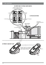
The doorphone system can be used to welcome and filter visitors, listen in to background sounds
at each access point and communicate with another handset.
It can also be used to remotely control:
• one or several electrical latches,
• one or several automatic gate control systems,
• one or several automatic garage door control systems,
• one or several lights.
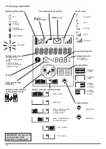
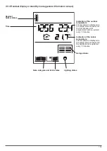
It also allows users to check the status of access points or lights using the screen on the handset
at any time. 
Several additional interior handset units can be added to the doorphone system (maximum of 4
per call button).

Foreword

Hager Security SAS hereby declares that the radioelectric equipment, references LCA01U, LCA01X,
LCB01X, MHF01X, MHF02X, MHF03X, MHF04X, MHF05X and MHF06X, complies with the requirements
of the following 2014/53/EU RE-D directive.
The full text of the EU declaration of conformity is available at the address: www.hager.com.

Non-binding document, subject to modification without notice.

Содержание LCP01U

Страница 1: ...listen in to background sounds at each access point and communicate with another handset It can also be used to remotely control one or several electrical latches one or several automatic gate control...

Страница 2: ...the radio link between the handset and the controller 200 6 Testing the radio range 203 7 Installing the interior handset unit 204 7 1 On a table 204 7 2 On a wall 204 8 Testing operation 208 8 1 Tes...

Страница 3: ...ll buttons tag reader 2 call buttons with keypad tag reader Connection of an electrical latch or lock Handset units can communicate with each other inter handset communication function Handset Base Ou...

Страница 4: ...e electrical locks or latches the gate motorisation system the automatic garage door control system 1 lighting 1 communication with another handset 2 doorphone programming Using the outdoor caller uni...

Страница 5: ...pplied Radio link creation LED 4 captive screws for closing the cover Cover Controller base Fixing bracket Connection terminal blocks Captive screws for bracket fixing Cable clamp do not remove Gromme...

Страница 6: ...over Garage control button 1 Lighting control button 1 Up and down scroll keys Left and right scroll keys Backlighting is activated whenever a button is pressed It goes out again after 5 seconds when...

Страница 7: ...Missed call no signal poor average good excellent Radio range lighting off lighting on Lighting status Garage side gate and latch status gate closed gate open gate 1 open 2 closed or gate half open if...

Страница 8: ...Lighting status Garage status Indication of the indoor temperature The temperature displayed is the temperature measured on the handset and is updated every 10 minutes Indication of the outdoor tempe...

Страница 9: ...the general price list and can be sent on request Some after sales service products and accessories such as MHU01X or MHU01U power packs LCH01X interior handset unit base LCH02X belt clip LCH03X hands...

Страница 10: ...ller sur certif LCB01F A0831A04823 LCB01F A0831A04823 On the back of the caller unit On the handset LCA01F A0831A04823 Coller sur certif 1 Unscrew the 4 cover screws and open the controller 2 Remove t...

Страница 11: ...ble is positioned in the designated slot Thread the cable through here Alternative cable passage IMPORTANT when installing the system the handset s must be charged on the base before it they can be us...

Страница 12: ...lternative guides Pozidriv 0 Pozidriv 0 8 Screw it back into the same place hence locking the base in table position 9 Close the base Pozidriv 2 10 Tighten the locking screw to prevent the base from b...

Страница 13: ...ttery is not sufficiently charged 1 If the battery is sufficiently charged You can now move on to the next chapter describing how to install the doorphone IMPORTANT the mains socket must remain access...

Страница 14: ...Follow steps 3 to 6 below for units without armoured cover 3 If the cable goes around the pillar pierce one of the cable knock outs with a cutter 4 Push the screw covers out using a flat screwdriver 5...

Страница 15: ...ith armoured cover 232 4 mm 145 mm 145 mm 160 4 mm 145 mm 145 mm 1 2 IMPORTANT use the label supplied and carefully position it in the space provided TIP you can print the labels using the software Et...

Страница 16: ...191 4 Pozidriv 2 6 3 5...

Страница 17: ...192 7 8 9 3 5...

Страница 18: ...193 11 10 12 IMPORTANT when the armoured cover is positioned on the unit there should be a 1 mm clearance use the shim for this purpose between the pillar and armoured cover Pozidriv 2...

Страница 19: ...sure the area is always clear place the controller as high up as possible 80 cm min make sure there are no obstacles between the controller installation point and the house where the handset s is are...

Страница 20: ...2 Pozidriv 2 1 To make it possible to thread the cables through for the outdoor caller unit external power supply motorisation system etc remove the grommets and pierce a hole with the same diameter...

Страница 21: ...the length of the cable supplied and then connect the wires to a branch box in accordance with the rules below up to 10 m including the remaining length of the original cable use 4 x 0 32 mm cross se...

Страница 22: ...uires an external power supply If a push button allowing manual control of the automatic system has already been installed connect terminal blocks 12 and 14 in parallel on this manual control input NC...

Страница 23: ...nal Position the 4 LR20 1 5 V batteries not supplied making sure they are the right way round The batteries are used as back up in the event of a mains power failure 3 5 IMPORTANT push the batteries i...

Страница 24: ...powered the outdoor caller unit lights up and beeps every 2 sec The radio link creation LED also lights up red for 2 sec If this is not the case check that the controller s batteries or external power...

Страница 25: ...hen The handset beeps for 2 sec 3 Programme the time 1 A set the first digit using the keys B set the next digit using the key C return to steps A and B to set the minutes and then once the desired ti...

Страница 26: ...o link creation mode by pressing The handset displays KEY 1 The radio link creation LED lights up orange IMPORTANT when using a translucent MHF01X or MHF02X outdoor caller unit and 1 button armoured c...

Страница 27: ...C beeps for 2 sec and The radio link has been created If an error occurs the handset displays It beeps 3 times and then automatically returns to the next screen Start the radio link creation procedure...

Страница 28: ...C C 3 You can hear what is happening around the outdoor caller unit at the selected access point Reception is good if at least 3 bars are displayed If this is not the case move the handset 4 Press on...

Страница 29: ...n to a wall position 1 Remove the handset from the base 2 IMPORTANT the removable transparent cover must be in place when fixing the unit to the wall If this is not the case clip it back on 3 Disconne...

Страница 30: ...tate the back of the base until it is in wall position 6 Unscrew the locking screw 7 Insert the screw here and tighten it Pozidriv 0 Pozidriv 0 Pozidriv 2 4 Unscrew the base locking screw 5 Open the b...

Страница 31: ...Check the power pack jack is in the right position 11 Thread the power cable into one of the guides at the back of the base Thread the cable through here Alternative cable passage 12 Fix the base to...

Страница 32: ...V Pozidriv 2 16 Place the handset on the base The handset beeps once C If necessary the icon flashes to show the handset is being charged Electrical shock hazard IMPORTANT the mains socket must remai...

Страница 33: ...e handset rings 1 except if it is in silent mode and the backlighting flashes The name of the access point calling 2 is displayed C 1 If there is no answer the handset rings for 20 sec factory setting...

Страница 34: ...utton press then enter the access code again For additional tests gate access listen in and inter handset communication functions etc please refer to the corresponding chapters in the user manual The...

Страница 35: ...activate the appropriate applications lighting automatic control system etc or respond according to their programming These applications or responses are also called functions A Receiver product can...

Страница 36: ...ight button on the handset is pressed this activates the lighting controlled by the output receiver for 5 minutes A radio link is created and a function is allocated to this radio link as part of the...

Страница 37: ...xamples By creating a radio link between a controller and an output receiver the following applications can be set up gate opening can switch on lighting to facilitate night time access and gate closi...

Страница 38: ...ate closed This event is displayed when the side gate closes as long as limit switches have been wired 5 Day breaking 1 This event is displayed when the day breaks Useful for switching off night light...

Страница 39: ...reen for 2 sec Otherwise start the procedure again The radio link has been created 5 Validate the procedure Press on the key IMPORTANT if an error occurs the radio link LED flashes red 3 times The rad...

Страница 40: ...as a transmitter Application examples By creating a radio link between the or keys on the handset and an output receiver the following applications can be set up Radio link n 1 Press once on the key t...

Страница 41: ...C C C 2 Switch to radio link creation mode 3 Select the function Information available in the receiver product manual Press on the or key Select a command from the following GARAGE 1 GARAGE 2 GARAGE...

Страница 42: ...e Press on the key The handset displays C C then C and beeps for 2 sec Garage or light icon displayed If an error occurs the handset displays It beeps 3 times and then automatically returns to the gen...

Страница 43: ...alling the doorphone you have created radio link n 1 e g handset programmed for the 1st call button and input 1 To create radio links n 2 n 3 n 4 and n 5 follow the procedure below Radio link n 2 2nd...

Страница 44: ...aller unit call button to call the handset C C Display the following screen using the keys C KEY 1 IMPORTANT If you are using an MHF01X or MHF02X translucent outdoor caller unit and a 1 button armoure...

Страница 45: ...green for 2 sec 4 The handset displays then and The radio link has been created beeps for 2 sec BEEP C C C If an error occurs the handset displays It beeps 3 times and then automatically returns to th...

Страница 46: ...reated between each one To do this proceed as follows IMPORTANT each handset can be linked via radio with a maximum of 7 other handsets C C C 1st handset 2nd handset 1 Switch the handset to radio link...

Страница 47: ...The handset displays C C then C and The radio link has been created beeps for 2 sec beeps for 2 sec If an error occurs the handset displays It beeps 3 times and then automatically returns to the gene...

Страница 48: ...ted between a handset and a controller To do this open the controller cover and proceed as follows C C C Handset Controller 1 Switch the handset to radio link test mode 2 Press or C Display the follow...

Страница 49: ...ays 3 The key is linked via radio to the controller side gate output The key is linked via radio to the controller latch output 6 After several seconds the handset exits radio link test mode and retur...

Страница 50: ...dio links created between a controller and a handset Controller Handset Outdoor caller unit 1 Press 2 Switch the handset to radio link deletion mode C C Display the following screen using the keys C T...

Страница 51: ...n for 2 sec 4 The handset displays C C then C beeps for 2 sec and The radio link has been deleted The outdoor caller unit beeps for 2 sec BEEP The radio link creation LED flashes orange If an error oc...

Страница 52: ...to factory programming This procedure is used to delete all the radio links and reset all handset and controller parameters to their factory value 1 Switch the handset to radio link deletion mode C C...

Страница 53: ...sec until the radio link LED stops flashing red The LED will then light up green for 2 sec The outdoor caller unit beeps for 2 sec The handset and controller have been returned to their factory settin...

Страница 54: ...he radio link LED lights up red for 2 sec the outdoor caller unit lights up and also beeps for 2 sec If this is not the case check the batteries have been correctly inserted Pozidriv 2 No reprogrammin...

Страница 55: ...e the handset back on its base in order to start it up 5 Programme the time using and The temperature display will be updated several minutes after the handset has been powered If necessary the icon f...

Страница 56: ...on is limited depending on the type and thickness of the walls or partitions through which they pass What should I do if I lose the display on my handset What should I do if the handset does not beep...

Страница 57: ...the batteries It is advisable to change the handset battery at the same time Why is the CHARGE HANDSET message displayed Put the handset on the base to charge it Why is the MEMORY FULL message display...

Страница 58: ...aller unit and the controller Control and powering of any type of low consumption 0 5 A max 12 V latches Control of safety ELV motorisation system able to operate with a 48 V DC 1 A dry contact relay...

Страница 59: ...234...

Страница 60: ...235...

Страница 61: ...805202 B Hager 04 19 www hager com Hager SAS 132 Boulevard d Europe BP 78 F 67212 OBERNAI CEDEX T l 333 88 49 50 50...

Отзывы: