background image

– 6 –

O

P E R A T I O N

POWER SWITCH

The POWER switch is located on the front panel of the amplifier. An internal lamp indicates when it is turned on.

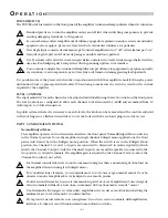
Standard practice is to turn the amplifier on last and off first when switching components to prevent
sending damaging transients to the speakers.

Es costumbre encender el amplificador de último y apagarlo de primero cuando se estan encendiendo/
apagando otros equipos, para así evitar el envío de transientes dañinas a los parlantes.

Il est de pratique courante de commencer par tourner l'amplificateur sur “off” et de terminer par “on,”
lorsqu'il s'agit de prévenir l'envoie de passages nuisible aux haut-parleurs.

Der Verstärker sollte als letztes Gerät eingeschaltet und als erstes Gerät wieder ausgeschaltet werden,
um eine Beschädigung der Lautsprecher durch spannungsspitzen zu vermeiden.

L'uso comune consiglia l'accensione dell'amplificatore per ultimo e lo spegnimento per primo quando
si accendono i vari componenti, per evitare l'invio di transitori danneggianti agli altoparlanti.

It is possible to leave the power switch in the on position and switch the amplifier remotely through a power
distribution block or preamp switched outlet. When doing so make sure the switch is rated for the current
required by the amplifier.

LEVEL CONTROLS

The input sensitivity for each channel can be adjusted individually using the level controls on the front panel.
The level controls are configured to allow each channel to be attenuated by –60dB and are marked from 10
(full output) to 0 (full attenuation).

In public systems where it is necessary to match levels, the knobs can be removed and the controls adjusted
with your fingers or a flathead screwdriver. Cover the holes with the enclosed plugs to restrict access.

INPUT CONFIGURATION SWITCH

Normal/Bridged Mono

The amplifier operates in two-channel mode when the front panel Normal/Bridged Mono switch is
in the Normal position. To use the amplifier in single channel, bridged mono applications, the front
panel switch must be in the Bridged mono position. When the switch is set in the Bridged Mono
position, the Channel 1 (+) and  (–) inputs are connected to Channel 2 in reversed polarity, which
inverts the Channel 2 output. Only the Channel 1 input is used, and the speaker is connected to the
two positive (+) output terminals. The amplifier gain is adjusted by the Channel 1 level control; the
Channel 2 control is not active.

For thermal considerations we do not recommend using less than a nominal eight ohm load on
the amplifier when running it in bridged mono.

Por consideraciones térmicas, no recomendamos el uso de una carga nominal menor de ocho
ohmios cuando el amplificador esté trabajando en el modo puente.

Pour de raisons thermales, nous ne recommandons pas d'envoyer à l'amplificateur, une charge de
valeur nominale inférieure à huit ohm, au moment du fonctionement en mode “mono.”

Um thermische Störungen zu vermeiden, empfehlen wir in der mono Brückenschaltung die
minimale Last von 8 Ohm nicht zu unterschreiten.

Per ragioni di natura termale non consigliamo l'uso di un carico nominale dell'amplifiactore
inferiore a 8 ohm nel caso di funzionamento monofonico ostruito.

!

!

!

!

!

!

!

!

!

!

Содержание trans-nova P4000

Страница 1: ...PROFESSIONAL POWER AMPLIFIER P4000 Installation Operation PROFESSIONAL POWER AMPL nova trans DESIGNED AND ASSEMBLED IN THE U SA...

Страница 2: ...of the equipment s plug be able to fully insert into the mating receptacle Never remove the round grounding pin on the plug in an attempt to mate to a two wire ungrounded receptacle use a grounding ad...

Страница 3: ...s CMRR 75dB at 1kHz Input Impedance 47 000 per phase balanced Input Sensitivity Range 710mV to 4V 8 per phase balanced 592mV to 4V 4 per phase balanced In Out Gain 29dB maximum 29dB minimum Gain Contr...

Страница 4: ...ATION Power Switch 6 Level Controls 6 Input Configuration Switch 6 Ground Switch 7 Short Circuit Protection 7 LED Indicators 7 Warm Up 7 Cleaning and Maintenance 7 TECHNICAL REFERENCE Field Service Co...

Страница 5: ...AMOND yields lower high frequency distortion without the sonic degradations associated with increasing the negative feedback We have been using MOSFETs in our power amplifiers since the 1970 s During...

Страница 6: ...ade in the U S A Audio Ground Chass Float C H 1 8 C A U T I O N RISK OF ELECTRIC SHOCK DO NOT OPEN WARNING DO NOT REMOVE COVER TO REDUCE THE RISK OF FIRE OR ELECTRIC SHOCK DO NOT EXPOSE THIS EQUIPMENT...

Страница 7: ...20cm hinter der Front des Verst rkers angebracht werden Per i sistemi ad armadio sono necessari due ventilatori direzionati in su collocati dai 10 ai 13 centimetri davanti all amplificatore Inadequate...

Страница 8: ...INPUT FROM SOURCE 1 2 3 GND 1 2 3 SHIELD SHIELD SHIELD INPUT The input jacks located on the back of the amplifier are dual function connectors which accept 1 4 Phone Tip Ring Sleeve or XLR plugs The 1...

Страница 9: ...dged amplifier shares the load between the two channels each channel will effectively drive half of the load Therefore for bridged mono operation we recommend using an eight ohm load as the minimum im...

Страница 10: ...by 60dB and are marked from 10 full output to 0 full attenuation In public systems where it is necessary to match levels the knobs can be removed and the controls adjusted with your fingers or a flat...

Страница 11: ...Lautsprechern oder in den Lautsprecherkabeln wird eine Schutzschaltung aktiv die den entsprechenden Kanal abschaltet Auf der Frontseite wird dies mit einer LED angezeigt Sollte dies einmal passieren b...

Страница 12: ...ently increases the power gain for the same bandwidth of the output stage by typically ten times over the conventional follower connection using the same MOSFET devices This increase in efficiency all...

Страница 13: ...erential Amp Q6 Q7 Current Mirror Q104 Q105 Positive Driver Cascode Q9 Q10 Feedback Network Drive Signal Local Feedback Bias Adjust R136 Positive Output Q4 Q15 Q115 B Output B Negative Output Q5 Q16 Q...

Страница 14: ...SC H E M A T I C DI A G R A M NOTES Unless specified otherwise 1 All resistors in ohms 2 All capacitors in microfarads 3 Channel 1 only shown 10...

Страница 15: ...PRI B PRI A BLK WHT BLK WHT 60 HZ NEUTRAL LINE BLK BLK WHT 15A SLO BLO WHT BLU BLU BLU AC4 AC3 CT2 WHT ORG RED BLU CT1 ORG ORG AC AC BRIDGE RECTIFIER GROUND GRN YLW AC CAPACITOR Model P4000CE 6 3A SLO...

Страница 16: ...12 PC BO A R D LA Y O U T PC 1487 C...

Страница 17: ...92 Q2 LM 317 Regulator SS 1375 Q3 LM 337 Regulator SS 1376 Q4 N Channel MOSFET SS 741T Q5 P Channel MOSFET SS 740T Q6 MMBT5088L SS 0114 DESIGNATOR VALUE PART ALL RESISTORS IN OHMS R1 56 2k 1 4W 1 RMP...

Страница 18: ...U4 LM339 Quad Comparator SS 730SM U5 LM339 Quad Comparator SS 730SM Power Switch SWH 1009 IEC Connector CC 0852 IEC Line Cord FAH 146 Transformer TT 1501 B Bridge Rectifier 25 Amp SSH 609 Thermistor 1...

Страница 19: ...ut devices have been changed or if the two channels of the amplifier do not run at the same temperature calibrating the bias is necessary Disconnect the power to the amplifier before removing the cove...

Страница 20: ...A on pin 7 the Output Signal is connected to the input of U4A on pin 6 The output of U4A goes low when pin 7 is low and pin 6 is near zero This condition indicating high drive voltage and low output v...

Страница 21: ...RMAL indicator Clipping Indicator SIGNAL Indicator CR4 LED Driver Q8 Signal Detector U5D Amplifier Output CLIP Indicator CR3 LED Driver U5C Clipping Detector U5A Drive Signal The CLIP indicator is dri...

Страница 22: ...d remove it from the amplifier Take the knobs off the level controls 2 Remove the 9 64 Allen screw located behind the rack ears and the three 9 64 screws on the bottom edge of the heatsink This frees...

Страница 23: ...rformed by anyone other than Hafler or an Authorized Hafler service center 3 Any product purchased outside the United States please contact your local dealer 4 Shipping charges to get the unit to Hafl...

Страница 24: ...tensiones deben proveer de la misma conecci n aterrada de tres hiles Es importante que el enchufe se pueda introducir comjpletamente en el recept culo Nunca remeva el pin de aterramiento en un intento...

Страница 25: ...consell e moins d tre en mesure de fournir la charge lectrique requise un fonctionement sans risque de tout mat riel reli 11 P RIODES DE NON UTILISATON Durant les p riodes de non utilisation la prise...

Страница 26: ...dies die erforderlichen Str me bertragen k nnen Benutzen Sie immer dreiadrige Verl ngerungskable 11 ZEITR UME IN DENE DAS GER AT NICHT GENUTZT WIRD Wird das Ger t ber einen l ngeren Zeitraum nicht ge...

Страница 27: ...uesti non garantiscono la potenza sufficiente per i corretto fuinzionamento degli apparati connessi E alters importante che vengano sempre impiegate prolunghe con la configurazaione a tre fili con ter...

Страница 28: ...6 97 HAFLER PROFESSIONAL A DIVISION OF ROCKFORD CORPORATION 546 SOUTH ROCKFORD DRIVE TEMPE ARIZONA 85281 U S A IN U S A 602 967 3565 IN CANADA 604 942 1001 IN EUROPE FAX 8503 9340 14 IN JAPAN FAX 81 5...

Отзывы: