background image

Wiring the Kit

If any components are unfamiliar to you, checking the pic-

torial diagram should quickly identify them. Or, the quantities,
and the process of elimination as you check the parts list, will
help. The pictorial diagram is necessarily distorted to some ex-
tent for clarity, so that you can trace every wire in a single
overall view for verification as you work. You may wish to
check off on the diagram as you solder each location.

To “prepare” a wire means to cut the designated length from

the coil of that color, and strip about 1/4" of insulation from each
end. The wire supplied in the kit is #18,  so you can set adjustable
wire-strippers accordingly. The transformer leads are #16  or
#18  and the line cord is #16.  Be careful that you do not nick the
wire when you strip it (that can happen more easily if you do not
use wire strippers) for that weakens it. The wire supplied in this
kit is “bonded stranded,” which provides exceptional flexibility
with resistance to breakage for easier use, and it is pre-tinned.

Whenever a connection is to be soldered, the instructions will

so state, or indicate by the symbol (S). If more than one wire is to
be soldered to 

the

 same terminal, they will be indicated by (S-2),

(S3),  etc. If soldering is not called for, other connections have
yet to be made to that terminal. They would be more difficult if
the connection was already soldered. Every connection in the
kit will be soldered when it is complete. After soldering a con-
nection, it is best to clip off any excess lead length to minimize
the possibility of a short circuit (as on switch lugs, where ter-
minals are very close together), and for a neat appearance.

Be sure that uninsulated wires cannot touch adjacent ter-

minals or the chassis metalwork.

The symbol (#) indicates a connection is to be made to that

point. When a lug number is specified without (#) it is simply a
locating reference.

When the instructions call for twisting two or three wires

together, the length of wire indicated anticipates a fairly tight,
uniform twist by hand, of three full turns every two inches. If
you find the wires too short, loosening the twist will gain some
needed length.

Handle the circuit boards carefully. They represent a major

part of the kit cost. Stand-up components, such as transistors,
should be checked when you install the module, to be sure all
leads are separated.

All of the active circuitry is contained on the PC-19 board,

which has been carefully tested to assure that it meets every

specification. Only the interconnection of power supply

elements is left to the builder. Take the time to be accurate and
neat, and you can be sure that your completed amplifier will
meet the performance of a factory assembled unit, and can con-
tinue to perform properly for years to come. Check your work,
and make sure the entire step has been completed before plac-
ing a check mark in the space provided, and continuing on to
the next step.

KEP nuts have been supplied as a convenience. These have

lockwashers attached, and the lockwasher always goes onto the
screw first. If the sheet metal screws have hex heads, you may

find it easier to first start them with a regular screwdriver, to set
the thread, and then use the more convenient nut driver, if one
is available.

Mechanical Assembly

1   When you unpack your kit, you will find that the

transformer, large capacitors, and the output assemblies
have been temporarily fastened to the chassis for safe
shipment. Disengage these, and include this hardware
with the rest when you check off the components
against the parts list in the back of the manual. We
recommend this check-off to be sure you have
everything, and to enable you to identify any unfamiliar
items by comparing them with the pictorial diagram. An
egg carton is ideal for keeping hardware items
separated.

A “set” of hardware includes one screw and one KEP nut (with
its attached lockwasher). Always install the lockwasher side of
the nut first. If the size of the hardware is not specified, use the #6
size. The smallest size is #4  and #lO  the largest. Always insert
the screw from the outside of the chassis.

It will simplify matters if you first separate the #4  nuts from the
#6  nuts, which have the same outside dimensions. A #4 screw

will pass through a #6  nut, aiding identification.

2   Select the four rubber feet, four sets of # 6  hardware, and

the chassis. Insert each screw through a foot so that the
head is recessed, and install the feet on the outside at
each corner hole.

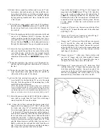
3   Select th e wo red output terminals. Install them in the

t

sequence shown below, in the two center holes LR and
RR marked 

' +’

 at the rear of the chassis. Before you fully

tighten the first nut, unscrew the cap to expose the hole
drilled through the threaded shaft. Connection of loud-
speaker wires will be easier if these holes are positioned
vertically. A nail through the hole will keep it positioned

while the hardware is tightened. Each connecting lug

should point downward before the last nut is secured. Be
sure both nuts on each terminal are 

tight, 

as they are dif-

ficult to reach when the amplifier is completed.

4  Select the two black output terminals and install them or

either side of the red ones, at LB and RR. Be sure the

shaft holes are vertical, the lugs point downward. and
each nut is tight.

6

Содержание DH-200

Страница 1: ...SEMBLY CAUTION IF THE SPEAKER FUSES BLOW SOME DISTORTED SOUND CAN BE HEARD THEREFORE IF AMPLIFIER MALFUNCTIONS ALWAYS CHECK FOR BLOWN FUSES FIRST serial number in all communications THE DAVID HAFLER COMPANY 5910 Crescent Boulevard Pennsauken New Jersey 08109 ...

Страница 2: ...e made a better choice The oversized power transformer and bridge rectifier the massive heat sinks the conservative operating levels of the MOSFET output devices all are evidence of the design efforts to achieve exceptional reliability simultaneously with state of the art sonics and specifications And this circuit is convertible to a high power monophonic amplifier with comparable stability and sp...

Страница 3: ...l content such as oscillation Failing evidence of this the amplifier may have malfunctioned Because of the very large heat sinks it is highly unlikely that any normal signal will cause the amplifier to overheat Loudspeaker Fuse Selection The DH 220 power amplifier is supplied with 2 amp fuses in the speaker lines Experience has shown that since an overload must exist for a few seconds for a fuse t...

Страница 4: ...s been internally modified for monophonic bridged operation the output is taken from the two red terminals only Then the black terminals are left unconnected Headphones are normally operated from the loudspeaker outputs but are usually connected through a junction box which provides switching from phones to speakers Such a box usually provides some added resistance to reduce the sensitivity of the...

Страница 5: ...bond When cool check the con nection by wiggling the wire If in doubt or if the connection is not shiny re heat the joint Excess solder may be removed from a connection by heating it and allowing the solder to flow onto the iron which is then wiped on the sponge ALL SOLDER USED MUST BE ROSIN CORE Never use acid core solder or any separate flux in electronic work Silver solder is also not suitable ...

Страница 6: ...lements is left to the builder Take the time to be accurate and neat and you can be sure that your completed amplifier will meet the performance of a factory assembled unit and can con tinue to perform properly for years to come Check your work and make sure the entire step has been completed before plac ing a check mark in the space provided and continuing on to the next step KEP nuts have been s...

Страница 7: ...front The switch snaps into chassis hole PS from the outside 13 q Select the AC line cord and the plastic strain relief Separate the two conductors for 2 Cut 1 off one of the two leads and strip 1 4 of insulation from each lead Twist the strands tightly and tin each end Make a sharp V in the cord 81 2 from the longest cut end by bending it back on itself Install the relief with the small end neare...

Страница 8: ...uter tabs while the wire does not protrude into the spade clamp area Tin the bare wire end Bend the shorter middle set of tabs tightly around the bare wire and then bend the longer tabs around the insulation Then flow solder into the joint around the bare wire keeping the solder away from the spade section 29 Prepare a 2 white wire Connect one end to FC lug 2 S Select another spade lug and solder ...

Страница 9: ...dered You will be making con nections from the top side to holes 3 5 6 7 8 and 10 Make sure the proper connection point is clear at each of these If it is filled with solder running the iron along the underside will uncover the hole and it may be cleared with a wooden toothpick Now position the right module with the breaker at the front when the long bottom row of eyelets is next to the chassis wi...

Страница 10: ...terminals and the ground lug should be brought together through most of their length 68 Check all your soldered connections especially those on the fuse clip lugs which are sometines difficult to solder to Clip off any excess bare wire which could short to adjacent lugs or the chassis Pay particular attention to the stranded wires from the transformer and line cord and check the power switch conne...

Страница 11: ...lp you locate the source of a prob lem may be obtained by calling the Technical Services Depart ment at 609 662 6084 8 a m 4 30 p m E T It is helpful to know the serial number of the unit and the results of any tests you have performed SERVICING AN AMPLIFIER MODULE If you are certain that the problem is confined to one of the amplifier modules comprising the circuit board heat sink and output tran...

Страница 12: ...uired when the multi voltage transformer is used This is supplied in kits which include the special transformer If the amplifier is operated with 200 to 240 volt tines the 7 amp line fuse which is supplied should be replaced with a 4 amp Slo Blo type fuse n VOLTAGE CHART measured with 120 volt line no signal with respect to the ground buss between the two capacitors in the power supply E B c E B c...

Страница 13: ...3 XA012 XA014 XPO14 WA016 AH326 XKOll XK012 SLlll HR144 XK018 XK016 TA123 Hardware Envelope 1 Lug solder type internal tooth 6 4 Lug solder type lO 3 Lug spade l 4 12 Nut 4 40 KEP 11 Nut 6 32 KEP 4 Nut l0 32 KEP 2 Nut l 2 for fuse holder 12 Screw machine 4 x 5 16 10 Screw machine 6 x l 2 4 Screw machine l0 x l 2 4 Screw l0 x l 4 SEMS 16 Screw sheet metal 6 x l 2 1 Screw machine 6 x 3 4 4 Washer fl...

Страница 14: ......

Страница 15: ...36 RZo13 RMo21 RM013 RC023 RC053 RZOll RZOll RD114 RDl15 RC013 RW012 RW013 RM053 RDll7 RDI 17 RDll4 RDl14 RDI 13 CP115 CP134 CP135 CP136 CP136 CC125 CC125 CN113 CP133 CP134 CP135 CL122 CP135 CL122 CP135 CP135 CP133 CP135 CP135 CC125 C22 C23 C40 1 C402 C403 C404 C405 C406 C407 C408 Dl D2 D3 D4 D5 D6 D7 D8 D9 DlO Dll D12 D13 D14 D15 D16 D40 1 0 1 mfd lOOV Film 0 1 mfd lOOV Film OOl mfd 25OV Film 680...

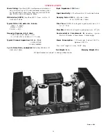
Страница 16: ... IO kHz 0 007 20 kHz 0 012 Frequency Response into 8 ohms 3 dB 2 Hz to 160 kHz at 1 watt O 0 5 dB 6 Hz to 60 kHz at 1 15 watts Rise Time 10 kHz 60 volts peak to peak square wave 10 to 9 0 2 5 us Slew Rate 10 kHz 60 volts peak to peak square wave 30 VI s Semiconductor Complement 26 transistors 8 power Mosfets 29 diodes 4 zener diodes 1 diode bridge Typical Channel Separation 20 Hz 75 dB 1 kHz 85 dB...

Страница 17: ......

Страница 18: ......

Страница 19: ......

Страница 20: ...The amplifier circuit can safely accommodate lower impedance loads of course The conversion which takes less than an hour involves only changes to the input wiring and installation of the switch with its mounting bracket and one resistor These instructions assume familiarity with the usual kit building descriptions and reminders For more details in this regard see the con struction section of your...

Страница 21: ...tal screws Select the switch and its 2 nuts lockwasher and indexing flat washer and the switch mounting bracket Install one nut all the way onto the switch collar and follow it with the indexing washer with its lugprojecting towards the handle lever Mount the switch on the bracket so that the lever points in the direc tion of the bracket flange and the indexing lug engages the locating hole in the...

Отзывы: