H
D
E
2
3
.0
1
.2
0
7
.xx.
xxx
1/32
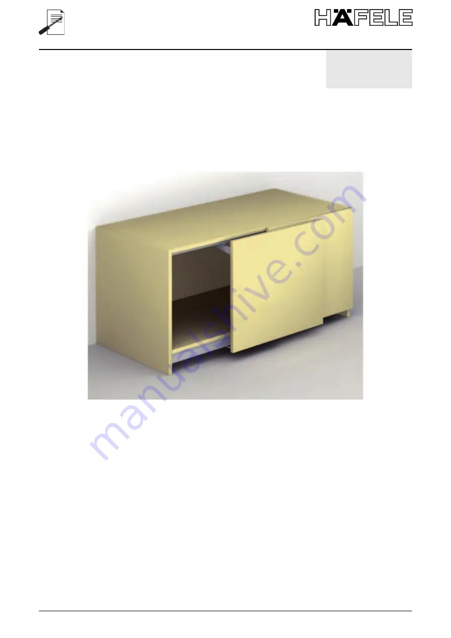
Finetta Flatfront S20 US FBFinetta Flatfront S20 US FBFinetta Flatfront S20 US FB
406.11.201-219406.11.301-319
Страница 1: ...HDE 23 01 2013 732 xx xxx 1 32 Finetta Flatfront S20 US FB Finetta Flatfront S20 US FB Finetta Flatfront S20 US FB 406 11 201 219 406 11 301 319 ...
Страница 2: ...ions FOR EACH DOOR C 1 1 no door adjuster blocks FOR EACH MECHANISM B 2 no guides for upper runner D 2 no upper brackets E 2 no cover plates for upper brackets F 4 no adhesive buffers 1 no 3 mm allen key THE QUANTITY OF THE FOLLOWING COMPONENTS WILL VARY ACCORDING TO THE LENGTH OF THE MECHANISM A no Either 4 6 or 8 fixing clips for upper guide runner Der Kunde wird eine Schachtel erhalten die folg...
Страница 3: ...3 32 HDE 23 01 2013 732 xx xxx 1 2 D E F A B C x 4 6 8 x 2 x 1 x 1 x 1 x 1 x 1 x 1 x 1 x 1 ...
Страница 4: ...e the cabinet is plumb and level 1 Den Behälter ins Lot brin gen 2 Applicare al cielo le clip in plastica A con viti TC 2 Fix the plastic clips A to the top panel with wood screws 2 Die Plastikklips A nach oben mit TC Sternkopf Schrauben befestigen Montage Assembly Montaggio ...
Страница 5: ... Position the sliding track 1 and fix it with self tapping screws 3 Die untere Schiene befes tigen 1 und sie mit den gewindeschneidenden Schrauben TPS fixieren 4 Inserire i bilancieri B nella guida del binario superiore 2 4 Insert the runners B in the track 2 4 Die Ausleger B in die Füh rung der oberen Schiene einsetzen 2 ...
Страница 6: ...re la guida superiore 2 nelle clip e fissarla con viti TC 5 Insert the upper track 2 into the clips and secure it with woodscrews 5 Die obere Führung 2 in die Klammern einsetzen und sie mit TC Schrauben be festigen Montage Assembly Montaggio ...
Страница 7: ...ore verticale e orizzontale B Regolatore verticale 4 Position the adjuster blocks C on the doors checking the correct arrangement A Vertical and horizontal regulator B Vertical regulator 4 Die Regler C an der Tür befestigen und die korrekte Anordnung prüfen A Waagrecht senkrecht Ausrichtungsbeschlag B Senkrecht Ausrichtungsbeschlag ...
Страница 8: ... upper bracket D with woodscrews 7 Die obere Halterung D mit TC Schrauben befestigen 8 Estrarre una coppia di car relli fino a totale apertura 8 Move one pair of carriages until it is fully open 8 Einen der Laufwagen bis zur vollkommenen Öffnung herausziehen Montage Assembly Montaggio ...
Страница 9: ...cks 9 Die Tür befestigen indem man vorher den Bolzen des oberen Auslegers in das Loch des Halters einsetzt und danach die Bolzen der unteren Wagen in den Reg lern einsetzt 10 Importante Bloccare l anta con chiave esagona le F 10 Important Fix the door onto the carriages using the 3 mm allen key F 10 Die Türen mit den Sechs kantschrauben fixieren F Ripetere la procedura dal punto 8 al punto 10 per ...
Страница 10: ...erno delle ante i paracolpi auto adesivi in dotazione F in battuta su base e cielo al centro del mobile 12 Apply the adhesive decel erating components pro vided to the inside of the doors F sealing the bot tom and top in the centre of the structure 12 Auf der Innenseite der Tür flügel die mitgelieferten selbstklebenden Puffer F oben und unten in der Mit te des Möbelstücks anbrin gen Montage Assemb...
Страница 11: ...rla in bolla agen do sui regolatori inferiori nell impronta di destra 13 Completely open the door and level it by adjusting the lower regulators in the rightslot 13 Die Tür vollkommen öffnen und sie ins Lot bringen in dem man die unteren Reg ler in der rechten Markie rung justiert Regolazioni Regulierung Adjustments 14 Allo stesso modo regolare la posizione verticale 14 In the same way adjust the ...
Страница 12: ...egolazione deve essere minima 15 If the gap between the doors is not parallel adjust it using the vertical adjust ers Attention any adjust ment must be minimal 15 Wenn der Spalt zwischen den Türen nicht parallel sein sollte die senkrechten Regler justieren Achtung die etwaige Regelung muss gering fügig sein Regolazioni Regulierung Adjustments ...
Страница 13: ...l regolatore cen trale nell impronta di sini stra 16 The doors can be adjusted horizontally by using the regulator in the left hand slot in the central adjuster block 16 Die Spaltenbreite zwischen den Türen und dem Korpus einstellen indem man den Regler in der linken Markie rung justiert 3 mm 3 mm 4 mm ...
Страница 14: ...nge the gap between the door and the cabinet use the adjust ment in the upper door bracket as follows A loosen the fixing screw B Adjust the cam below the fixing screw C Re tighten the fixing screw 17 Um seitlich den Spalt der Tür und dem Korpus einzu stellen wie folgt die oberer Halterung die an der Tür befestigt ist justieren A die Halteschraube lockern B auf den Exzenter unter der Schraube einw...
Страница 15: ...t cloth Avoid using products containing solvents and abrasive products Disposal Theproductsanditscomponents must not be disposed of in the environment for disposal please use public disposal systems Note The manufacturer reserves the right to modify any product without prior notice Reinigung Die Reinigung der Teile muss mit Wasser Seife und einem wei chen Tuch erfolgen Keine Pro dukte mit Lösungsm...
Страница 16: ...DE 23 01 2013 732 xx xxx 16 32 Motorantrieb für flächenbündiges zweitüriges Schiebesystem Motorization system for two door sliding mechanism Sistema di motorizzazione per movimento complanare a due ante ...
Страница 17: ...r close to the sides opening It is possible to require the motorization of the following mechanism Slider M35 Slider S20 Wall Cabinet Slider S20 Floor Cabinet Minimum cabinet depth Slider M35 Motorization mm 395 Slider S20 Wall Cabinet Motorization mm 340 Slider S20 Floor Cabinet Motorization mm 340 Maximum door weight Slider M35 35 kg Slider S20 Wall cabinet 20 kg Slider S20 Floor cabinet 20 Kg I...
Страница 18: ...pply and auxiliary control buttons single reset set up button D Supply unit with 200 cm long lead for connecting to mains and unit connection cable featuring rapid release connector 300 cm long Optional E Pair of light buttons to be fitted on outer side with connection cables to unit featuring rapid release connector 320 cm long F Remote control featuring remote control unit and relevant support w...
Страница 19: ...on ramp Soft stop HARDWARE Supply unit Transformer with thermal cutout Input 230VAC 50Hz Output 18VAC Power 40VA Control unit Supply input with fuse 18VAC Output to motors 5V DC encoder sensor supply 25V DC max voltage to motors Gearmotors Nominal torque 2 3 kgcm Nominal speed 375 rpm Power supply 24V DC Nominal current 750mA Rated power 12 70W Nice Receiver Power supply 10 28V DC Nice transmitter...
Страница 20: ...ing closing first of all of the left door and then of the right door Alternatively the set up can be performed by means of the remote control keeping the button 2 H pressed for five seconds This solution is preferable for customers who cannot easily access the control unit e g fitted furniture The set up can either be performed with both doors closed or with the left door open Dopo aver completato...
Страница 21: ...re on the door close to the sides where the buttons Q are recessed The door closing movement can be started By manual push R Alternatively by remote control S by pressing button 1 for the left door and button 3 for the right door respectively Alternatively by exercising a pressure on the button recessed in the side T In apertura la movimentazione dell anta può essere avviata Tramite spinta manuale...
Страница 22: ...tted in the previously worked outer sides The rapid release connectors must be fitted in the control unit inputs marked by plate P and more specifically in input P1 the lead whose button is fitted in the left outer side and in input P2 the lead whose button is fitted in the right outer side M Il cliente che lo desidera riceverà una coppia di pulsanti luminosi verdi L con cavi di collegamento alla ...
Страница 23: ...r loslassen 4 Once the storage phase has started any transmitter correctly recognised within the reception range of the radio is stored Carefully assess this aspect Disconnectthe power supply Loosenthe screws and remove the cover of the box of the control unit 2 Insertthe receiver in the connector inside the control unit 3 Restorethe power supply Press the button on the receiver and keep it presse...
Страница 24: ...rts to flash release the button 6 Whenthe LED on the receiver has stopped flashing press the button 3 on the remote control and keep it pressed when the LED on the receiver starts to flash release the button 7 Waitfor the LED on the receiver to light up for a few seconds Reposition the cover of the control unit box and tighten the screws Performthe set up Premeree tenere premuto il pulsante 1 sul ...
Страница 25: ...all estrazione Riattivarel alimentazione elettrica Eseguireil set up Loosen the M5x8 socket cap screws of the tightener and move the latter so as to slacken the belt V Loosenthe M6x35 socket countersunk screws or M6x12 socket countersunk screws in the case of the inner gearmotor and remove the gearmotor complete with fastening plate Z Replacethe gearmotor fastening plate assembly by proceeding in ...
Страница 26: ...release connectors of the light buttons must be fitted in the control unit inputs marked by the plate P and more specifically the lead whose button is to be fitted in the outer left side in the P1 input and the lead whose button is to be fitted in the outer right side in the P2 input the rapid release connector of the supply unit must be fitted in the control unit input marked by the plate A Recon...
Страница 27: ...a power plant built in accordance with applicable national standards and in particular the control unit power line must be equipped with a residual current circuit breaker Thissystem has been designed for non continuous use In the event of continuous use this should not exceed 15 minutes After such period the system must be allowed to rest for at least 15 minutes Donot force the movement of the do...
Страница 28: ... open or a door fails to close if left open Make sure power is reaching the control unit correctly Repeat the set up Make sure the quick coupling connectors of the gearmotors are correctly fitted in the control unit inputs Repeat set up Replace the control units and repeat set up One door fails to open or a door fails to close if left open Make sure the quick coupling connector of the gearmotor is...
Страница 29: ...remote control Repeat set up One of the two doors fails to open using side button only Make sure the quick coupling connectors of the buttons on the sides are correctly fitted in the control unit inputs Repeat set up Replace the button on the side Repeat set up Solo tramite telecomando le ante non si aprono o un anta non si chiude nel caso fosse stata lasciata aperta Verificare la batteria del tel...
Страница 30: ...by incorrect system installation Häfele disclaims all liability for damage to things or injuries to persons caused by incorrect system use Häfele disclaims all liability for damage to things or injuries to persons caused by the replacement of any system parts with other parts not supplied directly and therefore approved by Häfele The warranty shall be invalidated in the event of any system parts b...
Страница 31: ...31 32 HDE 23 01 2013 732 xx xxx Bestätigung Certifications Certificazioni ...
Страница 32: ...32 32 HDE 23 01 2013 732 xx xxx 2013 by Häfele GmbH Co KG Adolf Häfele Str 1 D 72202 Nagold www hafele com Subject to alterations Certificazioni Bestätigung Certifications ...