


37
Installation
3.8.7
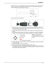
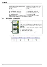
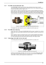
The 32003 insertion/extraction valve
The ORBISPHERE 32003 insertion/extraction valve (illustrated below) allows for sensor
removal and installation without having to drain the fluid in the line. It can withstand a pressure
of up to 20 bars, with the sensor in place or not.
Sensor insertion is made by inserting the sensor into the housing and tightening the retaining
collar until it stops. As the retaining collar is tightened, the valve will open to allow the sample to
flow past the sensor head. Remove the sensor by unscrewing the collar and pulling the sensor
out. As the collar is unscrewed, the valve will automatically close to avoid any sample spillage.
The diagram above right, shows the sensor in a sample line with the valve open.
3.8.8
The 33095 sensor housing
Another type of sensor housing (the ORBISPHERE 33095 housing) is available for use with the
K1200 sensor but requires that the sample flow be turned off prior to insertion or removal of the
sensor.
Sensor insertion is made by inserting the sensor into the housing and tightening the retaining
collar until it stops. Removal is made by unscrewing the collar and pulling the sensor out. Be
sure that the sample flow has been turned off before inserting or removing the sensor.
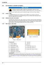
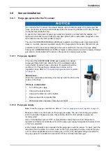
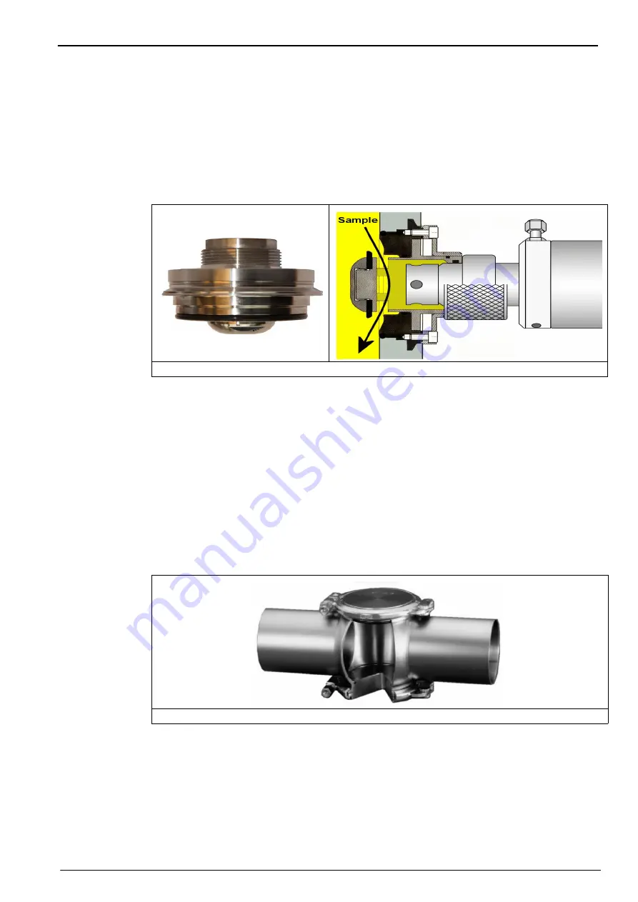
3.8.9
Tuchenhagen Varivent® in-line access unit
The following illustration shows the Tuchenhagen Varivent® In-Line Access Unit.
Purchasing a Tuchenhagen Varivent® in-line access unit, or an equivalent fitting with a 68 mm
flange diameter from the fitting manufacturer, is required to make use of the ORBISPHERE
model 32003 or 33095 sensor housing devices detailed above.
Figure 21 ORBISPHERE model 32003 insertion/extraction valve
Figure 22 Tuchenhagen Varivent® in-line access unit
Содержание Orbisphere 51 Series
Страница 1: ...DOC024 52 93116 ORBISPHERE Model 51x Analyzer with K1200 and TC Sensors USER MANUAL 02 2020 Edition 7...
Страница 5: ...4 Table of Contents...
Страница 19: ...18 Specifications...
Страница 48: ...47 Section 6 View Menu Figure 33 View menu...
Страница 52: ...51 Section 7 Measurement Menu Figure 36 Measurement menu...
Страница 66: ...65 Section 9 Inputs Outputs Menu Figure 40 Inputs Outputs menu...
Страница 68: ...67 Inputs Outputs Menu 9 4 Analog outputs Figure 41 Analog outputs menu...
Страница 75: ...74 Inputs Outputs Menu...
Страница 91: ...90 Communication Menu...
Страница 94: ...93 Section 12 Products Menu Figure 44 Products menu...
Страница 97: ...96 Global Configuration Menu...
Страница 98: ...97 Section 14 Services menu Figure 46 Services menu Part 1...
Страница 99: ...98 Services menu Figure 47 Services menu Part 2...
Страница 103: ...102 Services menu...


