Configure the relays and digital outputs
Select the alarms that trigger the relays and/or digital outputs. Configure the alarms before this task
is started. Refer to the sampler documentation.
1.
Push
MENU
.
2.
Select Programming>Alarm Programming.
3.
To select a system alarm (e.g., pump fault or full bottle):
a.
Select System Alarms>[Select System Alarm], then push
Next
.
b.
Select Action, then push
Edit
.
c.
Select an option, then push
OK
.
Note: When the system alarms that follow occur, the relay or digital output changes state for only
4 seconds. For the other system alarms, the relay changes state continuously while the alarm is active.
• Program Start
• Program End
• Bottle Change
• Sample Complete
• Missed Sample
• Purge Error
• Distributor Arm Error
• Pump Fault
Option
Description
Set Relay 1 (2, 3 or
4)
Sets the selected relay to change state when the alarm is active. The normally closed
(NC) contact of the relay opens when the alarm is active. The normally open (NO)
contact of the relay closes when the alarm is active. The alarm is recorded in the alarm
log.
Set Digital Output
1 (2, 3 or 4)
Sets the selected digital output to a closed switch or a logic low voltage when the
alarm is active. The alarm is recorded in the alarm log.
4.
To select a channel setpoint alarm:
a.
Select Channel Alarms>[Select Channel Alarm], then push
Next
.
Note: The number that follows a channel alarm identifies the source sensor. For example, Temp 2 is the
temperature measurement supplied by Sensor 2.
b.
Select Action, then push
Edit
.
c.
Select an option, then push
OK
.
Option
Description
Set Relay 1 (2, 3 or
4)
Sets the selected relay to change state when the alarm is active. The normally closed
(NC) contact of the relay opens when the alarm is active. The normally open (NO)
contact of the relay closes when the alarm is active. The alarm is recorded in the alarm
log.
Set Digital Output
1 (2, 3 or 4)
Sets the selected digital output to a closed switch or a logic low voltage when the
alarm is active. The alarm is recorded in the alarm log.
Configure the analog inputs
1.
Push
MENU
.
2.
Select Hardware Setup>AUX and I/O Port>Analog Inputs>[Select Analog Input]>Setup Wizard.
3.
Use the
DOWN
arrow to select Enable, then push
Next
.
4.
Obey the prompts on the screen. Refer to
for descriptions of the settings.
Note: To set the analog input settings and calibration to the factory defaults, select Restore Defaults.
16
English
Содержание IO9000
Страница 2: ...English 3 Français 19 Español 37 Português 54 中文 72 日本語 88 2 ...
Страница 7: ...Figure 2 Wall mounting English 7 ...
Страница 8: ...Figure 3 Mounting locations on the sampler 8 English ...
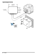
Страница 24: ...Figure 2 Montage sur un mur 24 Français ...
Страница 25: ...Figure 3 Emplacements de montage sur l échantillonneur Français 25 ...
Страница 42: ...Figura 3 Ubicaciones de montaje en el tomamuestras 42 Español ...
Страница 59: ...Figura 2 Montagem na parede Português 59 ...
Страница 60: ...Figura 3 Locais de montagem no amostrador 60 Português ...
Страница 76: ...图 2 墙面安装 76 中文 ...
Страница 77: ...图 3 采样仪上的安装位置 中文 77 ...
Страница 79: ...拆下护盖 按照如下图示步骤拆下护盖 布线概述 图 4 显示了布线连接以及保险丝位置 请参阅 图 5 准备和安装电线 中文 79 ...
Страница 93: ...図 3 サンプラーの取り付け場所 日本語 93 ...
Страница 95: ...カバーの取り外し 次の図の手順に示されているように カバーを取り外します 配線の概要 図 4 は ワイヤの接続部とヒューズの場所を示しています 配線を用意して取り付けるには 図 5 を 参照してください 日本語 95 ...
Страница 105: ......


