background image


13 

Installing or removing the server 

Installing the server 

Installing rails 

Install the inner rails to the server and the outer rails to the rack. For information about installing the 
rails, see the document shipped with the rails. 

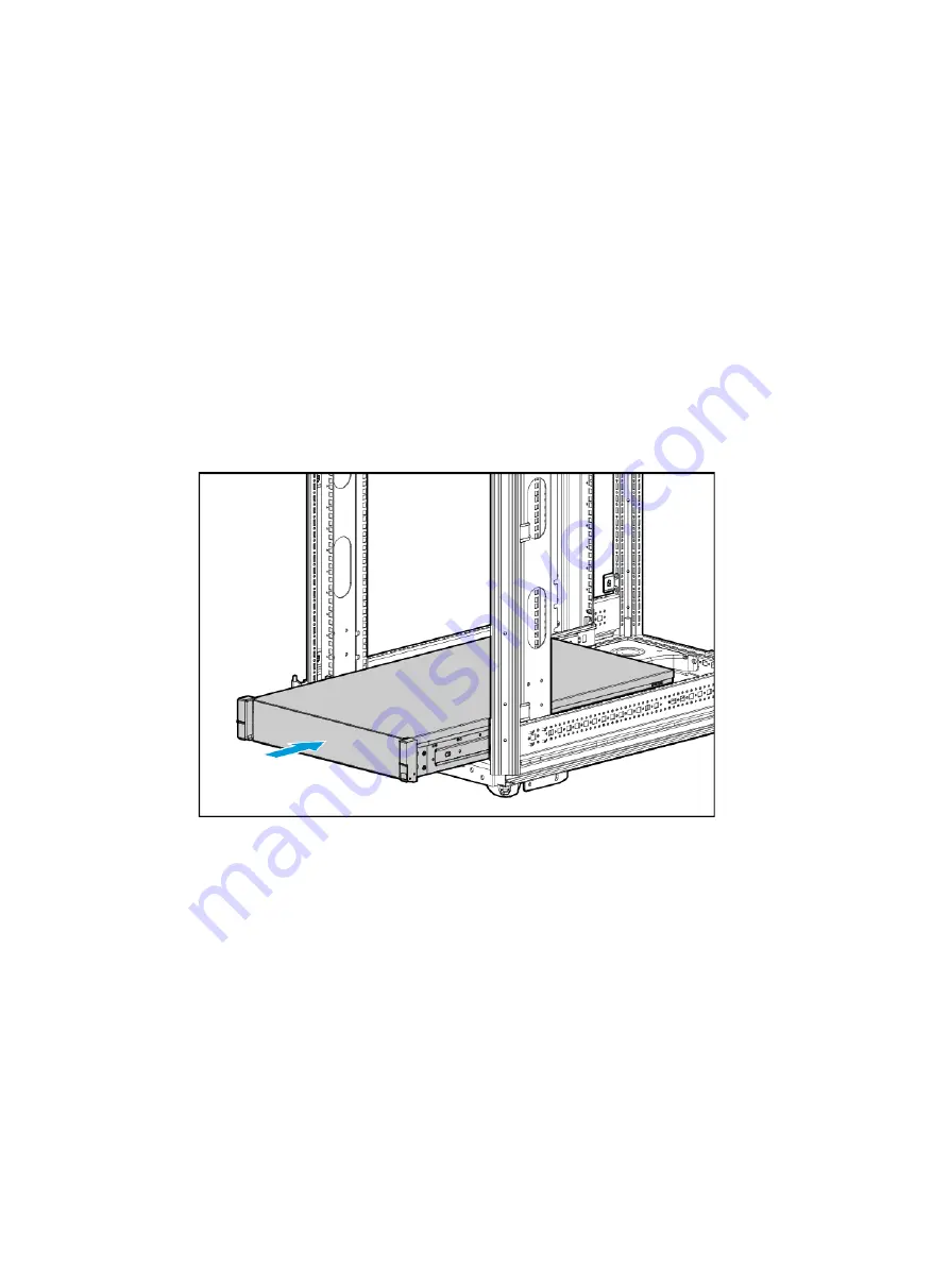
Rack-mounting the server 

1. 

Slide the server into the rack. For more information about how to slide the server into the rack, 
see the installation guide for the rails. 

Figure 3 Rack-mounting the server 


2. 

Secure the server. 

a. 

Push the server until the multifunctional rack mount ears are flush against the rack front 
posts, as shown by callout 1 in 

Figure 4

. 

b. 

Unlock the latches of the multifunctional rack mount ears, as shown by callout 2 in 

Figure 4

. 

c. 

Fasten the captive screws inside the chassis ears and lock the latches, as shown by callout 
3 in 

Figure 4

. 

Содержание UniServer R4300 G5

Страница 1: ...H3C UniServer R4300 G5 Server User Guide New H3C Technologies Co Ltd http www h3c com Document version 6W100 20220118...

Страница 2: ...espective owners Notice The information in this document is subject to change without notice All contents in this document including statements information and recommendations are believed to be accur...

Страница 3: ...red syntax choices separated by vertical bars from which you select one x y Square brackets enclose a set of optional syntax choices separated by vertical bars from which you select one or none x y As...

Страница 4: ...s a Layer 2 or Layer 3 switch or a router that supports Layer 2 forwarding and other Layer 2 features Represents an access controller a unified wired WLAN module or the access controller engine on a u...

Страница 5: ...Documentation feedback You can e mail your comments about product documentation to info h3c com We appreciate your comments...

Страница 6: ...talling the server 13 Installing rails 13 Rack mounting the server 13 Installing cable management brackets 14 Connecting external cables 14 Cabling guidelines 14 Connecting a mouse keyboard and monito...

Страница 7: ...nk from the OCP network adapter slot 38 Installing the blank to the OCP network adapter slot 39 Replacing the intelligent security bezel 39 Guidelines 39 Prerequisites 39 Removing the intelligent secu...

Страница 8: ...82 Prerequisites 83 Removing a GPU module 83 Installing a GPU module 84 Replacing a standard PCIe network adapter 85 Guidelines 85 Prerequisites 85 Removing a standard PCIe network adapter 85 Install...

Страница 9: ...ving the system battery 107 Installing the system battery 108 Connecting internal cables 109 Guidelines 109 Connecting drive cables 109 Connecting power cords for fan adapters 116 Connecting supercapa...

Страница 10: ...with the field servicing forbidden sign in any circumstances The RJ 45 ports on the server can be used only for Ethernet connections WARNING To avoid electrical shocks fire or damage to the equipment...

Страница 11: ...on standby button on the front panel the power supplies continue to supply power to some circuits in the server To remove all power for servicing safety you must first press the button wait for the s...

Страница 12: ...emoving them from their antistatic bags Avoid touching pins leads or circuitry Grounding methods to prevent electrostatic discharge The following are grounding methods that you can use to prevent elec...

Страница 13: ...t need to replace the battery When you replace the battery follow these safety guidelines Do not attempt to recharge the battery Do not expose the battery to a temperature higher than 60 C 140 F Do no...

Страница 14: ...e For installation limits for different rack depth see Table 2 Table 2 Installation limits for different rack depths Rack depth Installation limits 1000 mm 39 37 in The H3C cable management arm CMA is...

Страница 15: ...e front rack door 3 780 mm 30 71 in between the front rack posts and the rear of the chassis including power supply handles at the server rear not shown in the figure 4 800 mm 31 50 in server depth in...

Страница 16: ...erver specifications Equipment room height requirements To ensure correct operation of the server make sure the equipment room height meets the requirements as described in Appendix A Server specifica...

Страница 17: ...lectrostatic filters Hydrocarbons CnHn Automobile emissions fossil fuel processing tobacco smoke water treatment microbes paper mill and many other sources both natural and industrial Requirements of...

Страница 18: ...ipment room in a place with a high concentration of corrosive gases Make sure the equipment room is not connected to sewer sewage vertical shaft or septic tank pipelines and keep it far away from thes...

Страница 19: ...d use matt coating that does not produce powders Keep the equipment room clean and clean the air filters of the rack regularly Wear ESD clothing and shoe covers before entering the equipment room Keep...

Страница 20: ...talls or removes screws on chassis ears Flat head screwdriver Installs or removes captive screws inside multifunctional rack mount ears or replaces system batteries Phillips screwdriver Installs or re...

Страница 21: ...onnects to a third party USB Wi Fi module Xiaomi to provide a Wi Fi hotspot NOTE Support for the USB Wi Fi module depends on the server model USB Wi Fi module Xiaomi Serial console cable Connects the...

Страница 22: ...more information about how to slide the server into the rack see the installation guide for the rails Figure 3 Rack mounting the server 2 Secure the server a Push the server until the multifunctional...

Страница 23: ...let or outlet air vents of the fan modules heatsinks GPUs and PSUs To easily identify ports and connect disconnect cables make sure the cables do not cross Label the cables for easy identification of...

Страница 24: ...cable to the VGA connector on the monitor and fasten the screws on the plug 3 Connect the mouse and keyboard For a USB mouse and keyboard directly connect the USB connectors of the mouse and keyboard...

Страница 25: ...pter see Appendix A Specifications and Support Information 2 Determine type of the Ethernet cable Verify the connectivity of the cable by using a link tester If you are replacing the Ethernet cable ma...

Страница 26: ...the power receptacle of a power supply at the rear panel as shown in Figure 8 Figure 8 Connecting the power cord 2 Connect the other end of the power cord to the power source for example the power st...

Страница 27: ...power cord through the opening in the cable clamp and then close the cable clamp as shown by callouts 1 2 3 and 4 in Figure 10 Figure 10 Securing the AC power cord c Slide the cable clamp forward unt...

Страница 28: ...ment secure cables to left slide rails When multiple cable straps are used in the same rack stagger the strap location so that the straps are adjacent to each other when viewed from top to bottom This...

Страница 29: ...ver 3 Extend the server from the rack a Open the latches of the multifunctional rack mount ears as shown by callout 1 in Figure 13 b Loosen the captive screws inside the multifunctional rack mount ear...

Страница 30: ...utton Press the power on standby button to power on the server The server exits standby mode and supplies power to the system The system power LED changes from steady amber to flashing green and then...

Страница 31: ...o other servers Procedure Powering off the server from its operating system 1 Connect a monitor mouse and keyboard to the server 2 Shut down the operating system of the server 3 Disconnect all power c...

Страница 32: ...e server from the remote console interface 1 Log in to HDM For information about how to log in to HDM see the firmware update guide for the server 2 Log in to a remote console and then power off the s...

Страница 33: ...ower on the server For information about the procedures see Powering on the server 2 Verify that the health LED on the front panel is steady green which indicates that the system is operating correctl...

Страница 34: ...rd and user password for the BIOS setup utility you must enter the administrator password or user password each time you access the BIOS setup utility To obtain administrator privileges enter the admi...

Страница 35: ...er see the operating system installation guide for the server Updating firmware IMPORTANT Verify the hardware and software compatibility before firmware upgrade For information about the hardware and...

Страница 36: ...ltiple installation locations for certain components This document uses one location as an example Configurations in this document are for illustration only Common operations Removing the access panel...

Страница 37: ...will automatically slide in place as shown by callout 2 in Figure 16 c Optional To lock the access panel turn the screw on the locking lever 90 degrees as shown by callout 3 in Figure 16 Figure 16 Ins...

Страница 38: ...ir baffle into the chassis as shown by callout 2 in Figure 18 3 Close the hooks marked by blue trapezoids on the chassis air baffle as shown by callout 3 in Figure 18 Figure 18 Installing the chassis...

Страница 39: ...30 Figure 19 Removing the fan cage Installing the fan cage Gently place the fan cage into the chassis as shown in Figure 20 Figure 20 Installing the fan cage...

Страница 40: ...hassis as shown by callout 2 in Figure 21 Figure 21 Removing the T shape bracket Installing the T shape bracket 1 Place the T shape bracket onto the chassis with screw holes in the bracket aligned wit...

Страница 41: ...2 Installing the T shape bracket Removing the blank above the power supplies Hold both ends of the blank and pull it out of the chassis as shown in Figure 23 Figure 23 Removing the blank above the pow...

Страница 42: ...above the power supplies Removing the riser card blank over PCIe riser connector 1 or 2 The blank removal procedure is the same for PCIe riser connector 1 and connector 2 This section removes the bla...

Страница 43: ...edure is the same for PCIe riser connector 1 and connector 2 This section installs the blank over connector 1 as an example To install the riser card blank insert the blank into the chassis over PCIe...

Страница 44: ...of the chassis as shown in Figure 27 Figure 27 Removing the riser card blank over PCIe riser connector 4 Installing the riser card blank over PCIe riser connector 3 or 4 The blank installation procedu...

Страница 45: ...e riser card blank over PCIe riser connector 4 Removing a power supply blank Hold the blank by the holes with two fingers and then pull the blank out of the chassis as shown in Figure 29 Figure 29 Rem...

Страница 46: ...the blank into the slot until you cannot push it any further as shown in Figure 30 Figure 30 Installing a power supply blank Removing a PCIe module blank Pull the PCIe module blank out of the riser c...

Страница 47: ...the standout on the riser card into the blank notch to secure the blank as shown by callout 2 in Figure 32 Figure 32 Installing a PCIe module blank Removing the blank from the OCP network adapter slot...

Страница 48: ...ke the following ESD prevention measures Wear antistatic clothing Wear an ESD wrist strap and make sure it makes good skin contact and is reliably grounded Do not wear any conductive objects such as j...

Страница 49: ...Then pull the right edge of the bezel out of the groove in the right chassis ear to remove the security bezel as shown in Figure 36 Figure 36 Removing the intelligent security bezel Installing the int...

Страница 50: ...curity bezel Insert the key into the lock press and turn the key 90 degree anticlockwise and the pull out the key as shown in Figure 38 CAUTION To avoid damage to the lock hold down the key while you...

Страница 51: ...tion The pins in the processor sockets are very fragile and prone to damage Install a protective cover if a processor socket is empty For the server to operate correctly make sure processor 1 is in po...

Страница 52: ...sis air baffle For more information see Removing the chassis air baffle 5 Remove the processor heatsink a Loosen the four captive screws in a diagonal sequence as shown in Figure 39 Figure 39 Loosenin...

Страница 53: ...lips to unlock the heatsink c Lift the heatsink slowly to remove it as shown in Figure 41 CAUTION The pins on the processor socket are very fragile Never touch the pins Any damage to them might requir...

Страница 54: ...the processor and pull it out from the retaining bracket as shown by callout 2 in Figure 42 Figure 42 Removing the processor 7 Remove the processor retaining bracket from the heatsink a Release the f...

Страница 55: ...processor 1 Install the retaining bracket onto the heatsink a Close the ejector lever on the retaining bracket for secure installation of the processor b Align the alignment triangle on the retaining...

Страница 56: ...closed on the retaining bracket 2 Smear thermal grease onto the processor a Clean the heatsink Make sure no thermal grease remains on the heatsink top b Use the thermal grease injector to inject 0 6...

Страница 57: ...he processor and align the small triangle on the processor with the alignment triangle on the retaining bracket b Press one side of the processor against a retention clip on the retaining bracket c Us...

Страница 58: ...h the cut off corner of the processor socket and the pin holes in the heatsink with the guide pins on the processor socket Lower down the heatsink on the processor socket CAUTION To avoid damages to t...

Страница 59: ...ce Figure 52 Locking the heatsink c Use a T30 Torx screwdriver to fasten the four captive screws on the heatsink in a diagonal sequence CAUTION To avoid poor contact between the processor and the syst...

Страница 60: ...ment Log in to HDM and view the operating status of the processor to verify that the processor is operating correctly For more information see the HDM online help Replacing a DIMM WARNING To avoid bod...

Страница 61: ...IMM operates at the processor frequency For example for a DDR4 DIMM to operate at 3200 MHz you must also use a processor that can operate at 3200 MHz For the frequency of a DIMM or processor use the q...

Страница 62: ...se the schemes shown in Figure 56 Figure 57 and Figure 58 to populate the DIMM slots NOTE In Figure 56 Figure 57 and Figure 58 the black DIMM slots for example the F1 slot are grey colored and the whi...

Страница 63: ...4 DDR4 DDR4 DDR4 PMem 200 DDR4 DDR4 DDR4 DDR4 PMem 200 DDR4 DDR4 DDR4 DDR4 Number of DDR4 DIMMs Numer of PMem 200 DIMMs DIMM population DIMM slots processor 1 CH6 CH5 CH8 CH7 CH3 CH4 CH1 CH2 F0 F1 E0...

Страница 64: ...ull the DIMM out of the slot to remove the DIMM as shown in Figure 59 Figure 59 Removing a DIMM Installing a DIMM 1 Install the DIMM Align the notch on the DIMM with the connector key in the DIMM slot...

Страница 65: ...ress Enter Then verify the memory capacity of the DIMM If the memory capacity displayed is inconsistent with the actual capacity remove and then reinstall the DIMM or replace the DIMM with a new DIMM...

Страница 66: ...re information see Removing the fan cage 9 Disconnect all cables from the system board 10 Remove all components installed on the system board for example riser cards DIMMs and processors 11 Install pr...

Страница 67: ...hen slide the system board toward the server rear until the connectors for example USB connectors and the Ethernet port on it are securely seated as shown by callout 1 in Figure 63 NOTE The connectors...

Страница 68: ...it straight up and away from a socket as shown in Figure 64 Keep the cover for future use Figure 64 Removing the protective cover over a processor socket 4 Install the removed components for example...

Страница 69: ...ctor type SAS or SATA For efficient use of storage use drives that have the same capacity to build a RAID If the drives have different capacities the lowest capacity is used across all drives in the R...

Страница 70: ...panel to release the locking lever and then hold the locking lever and pull the drive out of the slot To remove an HDD press the button on the drive panel to release the locking lever Pull the drive 3...

Страница 71: ...se four screws to secure the drive into place as shown in Figure 67 Figure 67 Attaching the drive to the drive carrier 2 Install the drive a Press the button on the drive panel to release the locking...

Страница 72: ...drive LEDs see Appendix A Specifications and Support Information Adding an NVMe drive Guidelines Support for hot insertion of NVMe drives varies by operating system For compatibility with the operatin...

Страница 73: ...e RAID array if the old drive is full or the new drive is of a different model Installing an NVMe drive 1 Remove the security bezel if any For more information see Removing the intelligent security be...

Страница 74: ...s As a best practice install drives that do not contain RAID information If the installed drive contains RAID information you must clear the information before configuring RAIDs For more information s...

Страница 75: ...carrier Remove the screws that secure the drive and then remove the drive from the carrier as shown in Figure 71 Figure 71 Removing the drive carrier Installing an NVMe drive 1 Identify if the operati...

Страница 76: ...e four screws to secure the drive into place as shown in Figure 72 Figure 72 Attaching the drive to the drive carrier 3 Install the drive a Press the button on the drive panel to release the locking l...

Страница 77: ...Access the BIOS For more information see the BIOS user guide for the server Access the CLI or GUI of the server Observe the drive LEDs to verify that the drive is operating correctly For more informa...

Страница 78: ...rom the rack For more information see Removing the server from a rack 3 Remove the drives attached to the backplane For more information see Removing a SAS SATA drive 4 Remove the access panel For mor...

Страница 79: ...r supports multiple rear drive backplanes This section replaces a rear 2FF drive backplane as an example Prerequisites Take the following ESD prevention measures Wear antistatic clothing Wear an ESD w...

Страница 80: ...the notch on the backplane with the guide pin on the drive cage attach the backplane to the drive cage and slide the backplane until you cannot slide it any further Then fasten the captive screw See F...

Страница 81: ...information see Removing the server from a rack 3 Remove the access panel For more information see Removing the access panel 4 Disconnect all cables from the drive backplane 5 Remove a rear drive cage...

Страница 82: ...the right side of the drive cage against the chassis side panel place the drive cage into the chassis and use screws to secure the drive cage The procedures are similar for installing a rear 2SFF driv...

Страница 83: ...r cord For more information see Connecting the power cord 7 Power on the server For more information see Powering on the server Replacing riser cards and PCIe modules WARNING To avoid bodily injury fr...

Страница 84: ...ver For more information see Powering off the server 2 Remove the server from the rack For more information see Removing the server from a rack 3 Remove the access panel For more information see Remov...

Страница 85: ...hown by callout 1 in Figure 85 b Close the retaining latch on the riser card as shown by callout 2 in Figure 85 Figure 85 Installing a PCIe module onto the riser card 2 Install the riser card on the s...

Страница 86: ...module provides a flash card and a supercapacitor When a system power failure occurs this supercapacitor can provide power for a minimum of 20 seconds During this interval the storage controller tran...

Страница 87: ...compatibility matrix Standard storage controller Supercapacitor Supercapacitor installation location RAID LSI 9460 8i 2G BAT LSI G3 A In the supercapacitor container on the air baffle RAID LSI 9460 8i...

Страница 88: ...nformation see Removing the access panel 4 Disconnect all cables from the standard storage controller 5 Remove the standard storage controller a Remove the riser card where the standard storage contro...

Страница 89: ...a supercapacitor as shown in Figure 89 a Install the supercapacitor Tilt the supercapacitor and insert one end of the supercapacitor into the supercapacitor holder Pull the clip on the holder and inse...

Страница 90: ...he internal threaded studs supplied with the power fail safeguard module on the standard storage controller b Install the flash card on the standard storage controller Align the two screw holes in the...

Страница 91: ...lash card For more information see Connecting supercapacitor extension cables 7 Install the access panel For more information see Installing the access panel 8 Rack mount the server For more informati...

Страница 92: ...objects such as jewelry or watches When you replace a component examine the slot and connector for damages Make sure the pins are not damaged bent for example and do not contain any foreign objects Re...

Страница 93: ...ser card 2 Reconnect other cables to the riser card if any 3 Install the riser card on the server For more information see Installing a riser card and a PCIe module 4 Install the access panel For more...

Страница 94: ...ff the server 2 Disconnect cables from the standard PCIe network adapter 3 Remove the server from the rack For more information see Removing the server from a rack 4 Remove the access panel For more i...

Страница 95: ...n contact and is reliably grounded Do not wear any conductive objects such as jewelry or watches When you replace a component examine the slot and connector for damages Make sure the pins are not dama...

Страница 96: ...M 2 SSDs You can install the expander module in a PCIe slot provided by a riser card For more information see Connecting the SATA M 2 SSD data cables If you are installing two SATA M 2 SSDs install t...

Страница 97: ...information see Removing the access panel 4 Remove all fan modules For more information see Removing a fan module 5 Remove the fan cage For more information see Removing the fan cage 6 Remove the SATA...

Страница 98: ...nder module with the two internal threaded studs on the chassis put the expander module onto the chassis and then use screws to secure the expander module as shown in Figure 98 b Connect the SATA M 2...

Страница 99: ...do not contain any foreign objects Removing a dual SD card extended module 1 Power off the server For more information see Powering off the server 2 Remove the server from the rack For more informati...

Страница 100: ...d extended module Insert an SD card into the slot and gently press the SD card to secure it in the slot as shown in Figure 101 Figure 101 Installing all the removed SD cards 2 Install the dual SD card...

Страница 101: ...n contact and is reliably grounded Do not wear any conductive objects such as jewelry or watches When you replace a component examine the slot and connector for damages Make sure the pins are not dama...

Страница 102: ...from the extended module Gently press an SD card to release it and pull the SD card out of the slot Figure 104 Removing an SD card Installing an SD card 1 Install a new SD card Insert the SD card into...

Страница 103: ...the dual SD card extended module 3 Install the removed riser card cage 4 Install the access panel For more information see Installing the access panel 5 Rack mount the server For more information see...

Страница 104: ...tion see Removing the access panel 4 Remove the chassis air baffle For more information see Removing the chassis air baffle 5 Remove all the fan modules For more information see Removing a fan module...

Страница 105: ...ws that secure the cable protection plate as shown by callout 1 b Slide the plate towards the server front and then remove the plate as shown by callouts 2 and 3 c Take the chassis ear and the cable a...

Страница 106: ...shown by callouts 2 and 3 in Figure 110 c Fasten the two screws that secure the plate as shown by callout 4 in Figure 110 Figure 110 Installing the cable protection plate d Fasten screws that secure t...

Страница 107: ...r more information see Rack mounting the server 9 Connect the power cord For more information see Connecting the power cord 10 Power on the server For more information see Powering on the server Repla...

Страница 108: ...l a fan module Insert the fan module into the slot and press the module gently until it is secured in position as shown in Figure 114 Figure 114 Installing a fan module 2 Install the access panel For...

Страница 109: ...or TPM Once installed the module becomes a permanent part of the system board If you want to replace the failed TCM or TPM remove the system board and then contact H3C Support to replace the TCM or T...

Страница 110: ...r off the server For more information see Powering off the server 2 Remove the server from the rack For more information see Removing the server from a rack 3 Remove the access panel For more informat...

Страница 111: ...tLocker is enabled When using BitLocker always retain the recovery key password The recovery key password is required to enter Recovery Mode after BitLocker detects a possible compromise of system int...

Страница 112: ...tion see Powering off the server 2 Remove the server from the rack For more information see Removing the server from a rack 3 Remove the power cord from the power supply You can secure a power cord by...

Страница 113: ...present install the new power supply in the slot for the replaced power supply To install a power supply 1 Install a new power supply Orient the power supply so that the lettering on the label is upri...

Страница 114: ...To avoid bodily injury from hot surfaces allow the server and its internal modules to cool before touching them Removing the NVMe VROC module 1 Power off the server For more information see Powering o...

Страница 115: ...he NVMe VROC module connector on the system board as shown in Figure 121 Figure 121 Installing an NVMe VROC module 2 Install the access panel For more information see Installing the access panel 3 Rac...

Страница 116: ...more information see the BIOS user guide for the server Prerequisites Take the following ESD prevention measures Wear antistatic clothing Wear an ESD wrist strap and make sure it makes good skin conta...

Страница 117: ...y callout 2 in Figure 123 Figure 123 installing the system battery 2 Install the access panel For more information see Installing the access panel 3 Rack mount the server For more information see Rack...

Страница 118: ...If you cannot identify the cables by labels provided with the cables apply new labels to cables for easy identification Connecting drive cables Drive cables include SAS SATA data cables NVMe data cabl...

Страница 119: ...Connect NVMe data cables for the front 24LFF backplane Connect the SlimSAS connectors on the backplane to the SlimSAS connectors on the system board Figure 125 Connecting NVMe data cables for the fro...

Страница 120: ...backplane Figure 127 Connecting power cords for the front 24LFF backplane 5 Connect SAS SATA data cables the power cord and the AUX signal cable for the rear 12LFF backplane You can route the power c...

Страница 121: ...ord under system board 1 AUX data cable 2 SAS SATA data cable 1 3 SAS SATA data cable 2 4 Power cord Figure 129 Connecting the power cord for the rear 12LFF drive backplane power cord above system boa...

Страница 122: ...X data cable for 2LFF 4 Power cord for 2LFF 7 Connect SAS SATA data cables for the rear 4SFF Unibay drive backplane and the rear 2LFF drive backplane Figure 131 Connecting SAS SATA data cables for the...

Страница 123: ...le to introduce the cabling method For more information about the slot locations see Appendix A Specifications and Support Information To connect drive cables for the front 24LFF drives rear 12LFF dri...

Страница 124: ...plane as shown in Figure 128 and Figure 129 6 Connect power cords and AUX signal cables for the rear 2SFF and 4LFF drives backplanes Figure 134 Connecting power cords and AUX signal cables for the rea...

Страница 125: ...r adapters as shown in Figure 136 Figure 136 Connecting power cords for fan adapters 1 Power cord 1 2 Power cord 2 3 Power cord 3 4 Power cord 4 Connecting supercapacitor extension cables Figure 137 C...

Страница 126: ...SSD data cables Connecting the PCIe signal cables The RC 3FHFL 2U SW G5 riser card requires PCIe signal cables whose cabling method varies by riser card installation location Use Figure 139 and Table...

Страница 127: ...and PCIe slot on the riser card are unavailable For more information about connectors and slots for slave processors visit the query tool at http www h3c com cn Service Document_Software Document_Cen...

Страница 128: ...is used prepare a new one Keep the network topology up to date to facilitate network troubleshooting Maintenance tools The following are major tools for server maintenance Temperature and humidity met...

Страница 129: ...s appropriate The cables are in good condition and are not twisted or corroded at the connection point Viewing server status To view basic information and status of the subsystems of the server see Vi...

Страница 130: ...SSDs 2 Drive numbering 2 Drive LEDs 2 Drive backplanes 3 Front 24LFF drive backplane 18SAS SATA 6UniBay 4 Rear 12LFF SAS SATA drive backplane 5 Rear 2LFF SAS SATA drive backplane 5 Rear 4LFF SAS SATA...

Страница 131: ...loud computing IDC and enterprise networks built based on new generation infrastructure Figure 1 Chassis view Technical specifications Item Specifications Dimensions H W D Without a security bezel 174...

Страница 132: ...d SATA connectors One 8 SlimSAS connector One 4 SlimSAS connector 1 RJ 45 HDM dedicated port at the server rear 2 VGA connectors one at the server rear and one at the server front 1 serial port at the...

Страница 133: ...r SFF drive cage Installs rear SFF drives 14 Rear LFF drive cage Installs rear LFF drives 15 Power supply Supplies power to the server The power supplies support hot swapping and 1 1 redundancy 16 Cha...

Страница 134: ...des support for the supercapacitor 33 Chassis open alarm module Detects if the access panel is removed The detection result can be displayed from the HDM Web interface Front panel Front panel view of...

Страница 135: ...LED Steady green The system is operating correctly or a minor alarm is present Flashing green 4 Hz HDM is initializing Flashing amber 1 Hz A major alarm is present Flashing red 1 Hz A critical alarm i...

Страница 136: ...at 1 Hz A pre alarm is present Flashing amber 1 Hz A major alarm is present Flashing red 1 Hz A critical alarm is present UID All beads flash white 1 Hz The firmware is being upgraded or the system is...

Страница 137: ...h 6 3 PCIe riser bay 3 PCIe slots 7 and 8 4 Optional 2SFF drives 5 Power supply 2 6 Power supply 1 7 Two USB 3 0 connectors 8 VGA connector 9 BIOS serial port 10 HDM dedicated network port 1Gbps RJ 45...

Страница 138: ...present on the port Off No link is present on the port Activity LED of the Ethernet port Flashing green 1 Hz The port is receiving or sending data Off The port is not receiving or sending data Power...

Страница 139: ...the server has failed Establish a GSM modem or encryption lock connection USB connector USB 3 0 Connects the following devices USB flash drive USB keyboard or mouse USB optical drive for operating sys...

Страница 140: ...PCIe X32 3 System battery 4 OCP 3 0 adapter connector OCP3 0 5 SlimSAS port 1 8 SATA SATA PORT 6 SlimSAS port 2 4 SATA SSATA PORT 7 Rear drive backplane AUX connector 9 AUX9 8 GenZ port 2 SATA M 2 CD...

Страница 141: ...1 B2 x8 PCIe4 0 for processor 2 NVMe B1 B2 27 Fan connector 1 J61 reserved 28 LP SlimSAS port B3 B4 x8 PCIe4 0 for processor 2 NVMe B3 B4 29 Power connector 6 PWR6 30 Drive backplane AUX connector 5 A...

Страница 142: ...starts up with the default BIOS settings at the next startup CAUTION The server cannot start up when the switch is turned on To avoid service data loss stop running services and power off the server b...

Страница 143: ...13 Figure 10 System board DIMM slot layout Fan adapters Fan adapter components Figure 11 shows the fan adapter layout Figure 11 Fan adapter components...

Страница 144: ...6 NOTE The number of a fan module or fan module power connector varies by the fan module slot that holds the fan adapter For example fan module connector 1 3 represents fan module connector 1 if the a...

Страница 145: ...el Ice Lake processor model suffixes Suffix Description N NFV Optimized T High T case U Single Socket V SaaS Optimized SKU for orchestration efficiency targeting high density lower power VM environmen...

Страница 146: ...IMM rank classification label description Callout Description Remarks 1 Capacity Options include 8GB 16GB 32GB 2 Number of ranks Options include 1R One rank Single Rank 2R Two ranks Dual Rank A 2R DIM...

Страница 147: ...the front Figure 14 Drive numbering at the rear Drive LEDs The server supports SAS SATA and NVMe drives of which SAS and SATA drives support hot swapping and NVMe drives support hot insertion and mana...

Страница 148: ...ff Steady green The drive is present but no data is being read or written to the drive Off Off The drive is not securely installed Table 14 NVMe drive LED description Fault UID LED status Present Acti...

Страница 149: ...talled at the server front to support 24 3 5 inch SAS SATA drives With an integrated Expander chip the drive backplane can provide six downstream connectors besides the two x8 Mini SAS HD upstream con...

Страница 150: ...attached to the connector can manage all SAS SATA drives on the backplane and the backplanes connected through the downstream connectors If two controllers are attached the controller attached to the...

Страница 151: ...FF SAS SATA drive backplane can be installed at the server rear to support four 3 5 inch SAS SATA drives Figure 19 Rear 4LFF SAS SATA drive backplane 1 AUX connector AUX 2 Power connector PWR 3 x4 Min...

Страница 152: ...2 4 x4 Mini SAS HD connector SAS PORT 5 Power connector PWR Riser cards To expand the server with PCIe modules install riser cards on the PCIe riser connectors Riser card guidelines Each PCIe slot in...

Страница 153: ...L Maximum power supplied per PCIe slot 75 W Figure 22 RC 2HHHL R3 2U G5 riser card 1 PCIe slot 8 2 PCIe slot 7 RC 3FHFL 2U G5 Item Specifications PCIe riser connector Connector 1 or 2 PCIe slots Conne...

Страница 154: ...ctors PCIe riser connector 1 SlimSAS port 1 x8 SlimSAS port connected to LP SlimSAS connector A1 A2 on the system board for processor 1 providing a x16 PCIe link for slot 1 together with SlimSAS port...

Страница 155: ...layout of the fan modules in the chassis The server can adjust the fan rotation speed based on the server temperature to provide optimal performance with balanced ventilation and noise During system P...

Страница 156: ...shows the PCIe slot numbers Figure 26 PCIe slot numbering when riser cards are installed at the rear PCIe modules Typically the PCIe modules are available in the following standard form factors LP Low...

Страница 157: ...s a built in flash card you can order only a supercapacitor Embedded VROC controller Item Specifications Type Embedded in PCH of the system board Number of internal ports 12 internal SAS ports compati...

Страница 158: ...erating system The obtaining method varies by OS For Linux execute the lspci command If Linux does not support the lspci command by default you must execute the yum command to install the pci utils pa...

Страница 159: ...to 70 C 40 F to 158 F Operating humidity 8 to 90 noncondensing Storage humidity 5 to 95 noncondensing Operating altitude 60 m to 3000 m 196 85 ft to 9842 52 ft The allowed maximum temperature decrease...

Страница 160: ...ans are used GPU modules are not supported When standard fans are used GPU modules are not supported The following hardware options are not supported Standard fans NVMe drives and GPU modules at the r...

Страница 161: ...2 For product recycling services contact New H3C at Tel 400 810 0504 E mail service h3c com Website http www h3c com...

Страница 162: ...ware Device Management is the server management control unit with which administrators can configure server settings view component information monitor server health status and remotely manage the ser...

Страница 163: ...ent of the overall height of racks as well as equipment mounted in the racks UniBay drive backplane A UniBay drive backplane supports both SAS SATA and NVMe drives V VMD VMD provides hot removal manag...

Страница 164: ...it G GPU Graphics Processing Unit H HBA Host Bus Adapter HDD Hard Disk Drive HDM Hardware Device Management I IDC Internet Data Center iFIST integrated Fast Intelligent Scalable Toolkit K KVM Keyboard...

Страница 165: ...Form Factor sLOM Small form factor Local Area Network on Motherboard SSD Solid State Drive T TCM Trusted Cryptography Module TDP Thermal Design Power TPM Trusted Platform Module U UID Unit Identificat...

Страница 166: ...rk adapters Make sure the software versions are as required BIOS 5 15 or higher HDM 2 29 or higher CPLD V2002 or higher Performing hot removal This section removes the OCP network adapter in slot 16 a...

Страница 167: ...and If no output is displayed the OCP network adapter has been disconnected Figure 3 Identifying OCP network adapter status 5 Replace the OCP network adapter 6 Identify whether the OCP network adapter...

Отзывы: