5
To connect your router to the network through a twisted pair cable:
1.
Connect one end of the twisted pair cable to the RJ-45 Ethernet port of your router.
2.
Connect the other end of the twisted pair cable to the RJ-45 Ethernet port of the access device
in the network.
3.
Check that the port LED status is correct.
For more information about the LED status, see "Appendix C LEDs."
Connecting your router to the network through optical fibers
WARNING!
Disconnected optical fibers or transceiver modules might emit invisible laser light. Do not stare into
beams or view directly with optical instruments when the switch is operating.
Before connecting optical fibers to a fiber port, install a transceiver module in the port. For
information about installing transceiver modules, see "(Optional) Installing transceiver modules". For
more information about optical fibers, see "Optical fiber."
To connect your router to the network through an optical fiber:
1.
Install the transceiver modules into the fiber ports of the router and the peer device.
2.
Remove the dust covers of the optical fiber connectors, and clean both ends of the optical fiber.
3.
Connect the optical fiber to the transceiver modules:
a.
Remove the dust plugs of the transceiver modules.
b.
Connect one end of the optical fiber to the transceiver module in the router.
c.
Connect the other end to the transceiver module in the peer device.
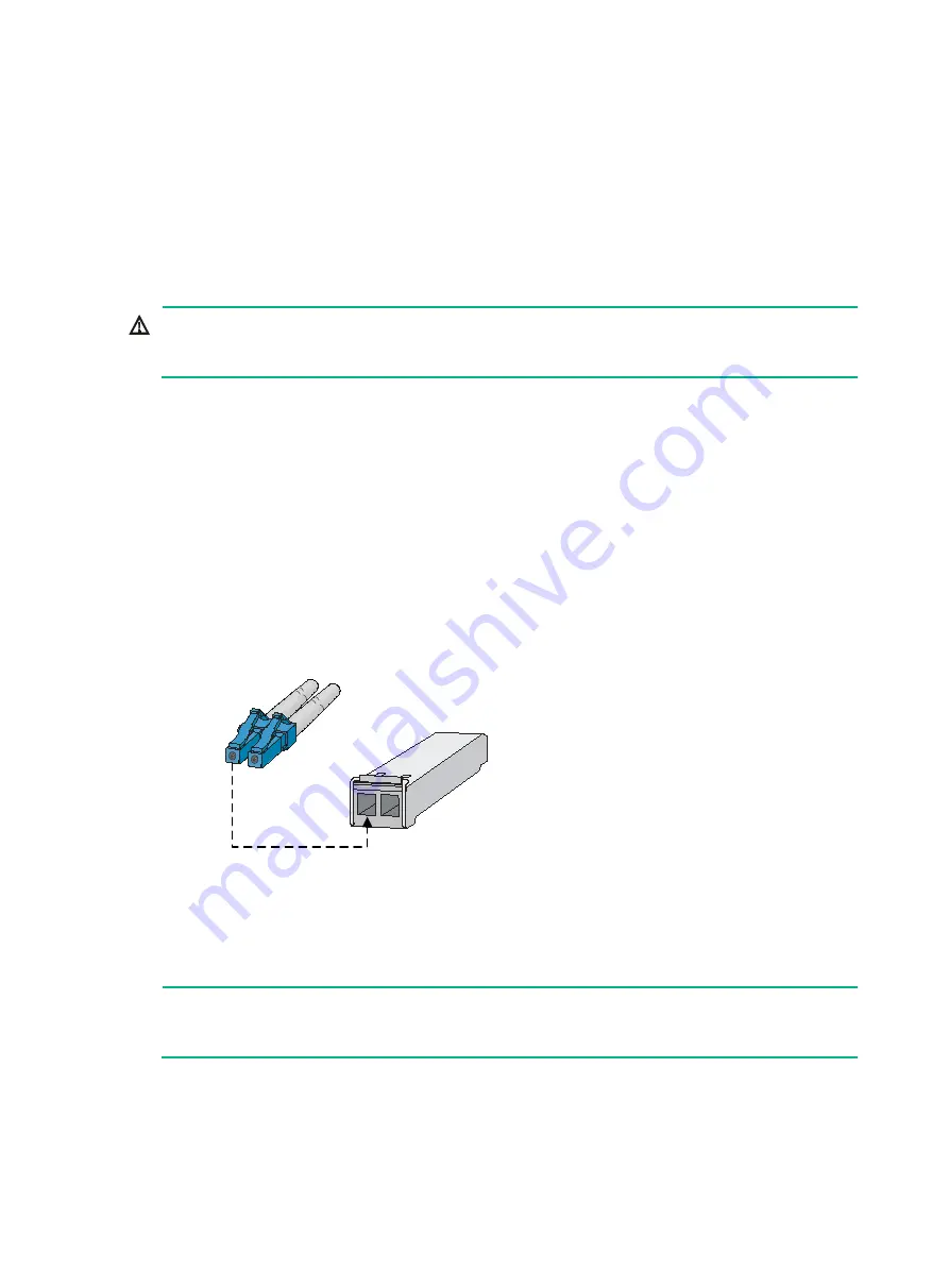
Figure 2 Connecting an LC optical fiber connector to an SFP module
4.
Verify that the port LED status is correct.
For more information about the LED status, see "Appendix C LEDs."
NOTE:
The transceiver modules each require two optical fibers. The transmitter (TX) port on one end must
connect to the receiver (RX) port on the other end.
Testing connectivity
When the router is connected to the network, use the
ping
or
tracert
command to test the
network connectivity. For more information about the two commands, see system maintenance and
LC plug
SFP module
Содержание SR8800-F
Страница 49: ...6 debugging commands in H3C SR8800 F Routers Network Management and Monitoring Command Reference ...
Страница 126: ...6 Figure 4 E1 cable 1 HM96 RJ 45 ...
Страница 127: ...7 Figure 5 E1 cable 2 HM96 SMB ...
Страница 148: ...12 Figure 14 Example of a device label ...


