


2-16
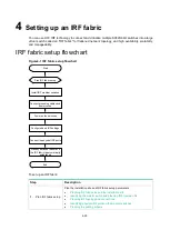
Figure2-16 Connecting the grounding cable to a grounding strip
(1) Hex nut
(2) Ring terminal
(3) Grounding post
(4) Grounding strip
Installing/removing fan trays
CAUTION:
The switch has three fan tray slots. For adequate heat dissipation, follow these guidelines:
•
The switch is provided with the fan tray slots empty. Before powering on the switch, make sure all
fan tray slots have fan trays installed and the fan trays are the same model.
•
Make sure each slot has a module or filler panel installed when the switch is operating.
•
If one fan tray fails when the switch is operating, replace the fan tray immediately and keep the
failed fan tray in position before the replacement. If two fan trays fail, finish replacing at least one
fan tray within 1 minute. Replace the fan trays one after another. Do not remove them
simultaneously.
The switch uses a front-rear air aisle. It can provide airflow from the power supply side to the port
side or from the port side to the power supply side by using different fan trays.
The LSWM1BFANSC, LSWM1BFANSC-SN, LSWM1BFANSCB, and LSWM1BFANSCB-SN fan
trays are available for the switch. The LSWM1BFANSC or LSWM1BFANSC-SN fan tray intakes air
from the fan tray panel. The fan tray handles are blue. The LSWM1BFANSCB or
LSWM1BFANSCB-SN fan tray exhausts air from the fan tray panel. The fan tray handles are red.
Select fan trays for the switch based on the airflow requirements. For the fan tray specifications, see
H3C S9820-64H Switch Hardware Information and Specifications
.
The installation and removal procedures are the same for the fan trays. The following installation and
removal procedures use the LSWM1BFANSC fan tray as an example.


