background image


30 


Execute the 

display irf configuration

 command to verify the basic IRF settings. 

For more information about configuring basic IRF settings, see 

IRF Configuration Guide

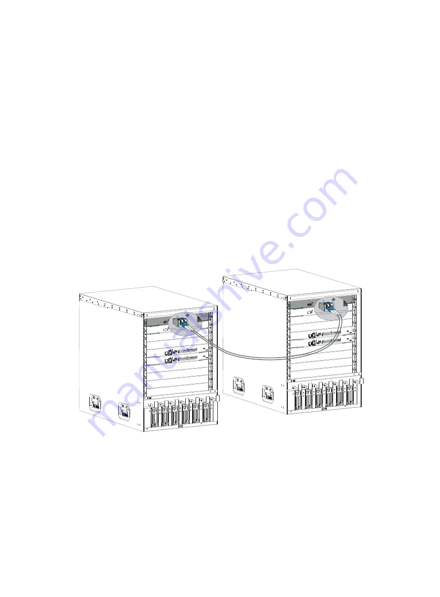
Connecting the physical IRF ports 

Follow these guidelines when selecting transceiver modules and cables:  


Use XFP transceiver modules and fibers to connect XFP ports. 


Use SFP+ transceiver modules and fibers for long-haul connection, or use SFP+ cables to connect 
SFP+ ports for short-haul connection. 


When connecting XFP/SFP+/CFP ports, connect the transmit port of an XFP/SFP+/CFP transceiver 
module at one end to the receive port of an XFP/SFP+/CFP transceiver module at the other end. 


Use QSFP+ transceiver modules and fibers for long-haul connection, or use QSFP+ cables to 
connect QSFP+ ports for short-haul connection. 


Use CFP transceiver modules and fibers to connect CFP ports. 


The transceiver modules at the two ends of an IRF link must be of the same type. 

For more information about installing transceiver modules, see "Installing FRUs." For more information 
about connecting fibers, see "Connecting your switch to the network." 

Figure 23


Connecting two IRF member switches 


Verifying the IRF fabric configuration 

After you finish configuring basic IRF settings and connecting IRF ports, verify the basic functionality of 

the IRF fabric, as follows: 

1.


Log in to the IRF fabric through the console port of any member switch. 

2.


Create a Layer 3 interface, assign it an IP address, and make sure the IRF fabric and the remote 

network management station can reach each other. 

Содержание S7508E-X

Страница 1: ...H3C S7508E X Switch Installation Guide Hangzhou H3C Technologies Co Ltd http www h3c com Document version 6PW106 20130918...

Страница 2: ...d All other trademarks that may be mentioned in this manual are the property of their respective owners Notice The information in this document is subject to change without notice Every effort has bee...

Страница 3: ...tions used in this documentation set Command conventions Convention Description Boldface Bold text represents commands and keywords that you enter literally as shown Italic Italic text represents argu...

Страница 4: ...ntial information NOTE An alert that contains additional or supplementary information TIP An alert that provides helpful information Obtaining documentation You can access the most up to date H3C prod...

Страница 5: ...s 12 Installing the power cable management brackets 12 Installing the mounting brackets 13 Installing an air filter optional 14 Mounting the switch to the rack 14 Mounting the switch on a workbench or...

Страница 6: ...your switch to the network through optical fibers 40 Testing connectivity 42 Troubleshooting 43 Troubleshooting methods 43 Troubleshooting the system 43 Configuration terminal problems 43 Troubleshoo...

Страница 7: ...Patch cord 89 Pigtail cord 89 Fiber connector 89 Precautions 89 SFP cable 90 QSFP cable 90 QSFP to SFP cable 91 Appendix E Cabling recommendations 92 General cabling requirements 92 Correct use of la...

Страница 8: ...iv Index 102...

Страница 9: ...the work area of possible hazards such as ungrounded power extension cables missing safety grounds and moist floors Locate the emergency power off switch in the room before installation Shut the power...

Страница 10: ...used indoors To ensure that the switch works correctly and to prolong its service lifetime the installation site must meet the following requirements Weight support requirements IMPORTANT When evalua...

Страница 11: ...leanness requirements Maintain appropriate cleanness in your equipment room Dust is a hazard to the operating safety of your switch Dust buildup on the chassis may result in electrostatic adsorption w...

Страница 12: ...ch Power supply requirements Perform the following steps to satisfy the power supply requirements of the S7508E X Switch 1 Calculate the system power consumption The system power consumption of an S75...

Страница 13: ...and the headroom in the equipment room is no less than 3 m 9 84 ft Make sure the rack has enough space height and depth to install your switches For more information about switch specifications see Ap...

Страница 14: ...ols ESD wrist strap hair brush tweezers paper knife hand bellows electric iron solder wire ladder cable stripper vacuum cleaner crowbar and rubber hammer Tools for fiber optic cleaning Lint free paper...

Страница 15: ...nient for moving Attaching slide rails and cage nuts to the rack Installing slide rails If the rack has slide rails skip this section Before you attach slide rails to the rack verify that The slide ra...

Страница 16: ...ide rail Mount this end to the front right rack post 2 Mark the position on the rack for installing the slide rail a Make sure the bottom edge of the slide rail aligns with the middle of the narrower...

Страница 17: ...al area between holes 3 Install six cage nuts in the square holes in each rack post as shown in Figure 4 Figure 4 Installing a cage nut 4 Align the installation holes on the front end of the slide rai...

Страница 18: ...de rail touch the cage nuts on the rear rack post Then screw in screws and fasten Install a screw in each mounting hole of the slide rail to ensure its weight bearing capacity 6 Repeat steps 4 and 5 t...

Страница 19: ...tall cage nuts to the front square holed brackets of the rack 1 Determine the placement of the cage nuts according to the holes on the mounting brackets and the mounting position of the slide rails as...

Страница 20: ...brackets signal cable and power cable management brackets for cabling the switch The signal cable management brackets have been installed to the mounting brackets when the switch was shipped For how...

Страница 21: ...ment bracket 3 Power cable management bracket 4 Screws for fixing the power cable management bracket to the chassis Installing the mounting brackets Before installing the switch to the rack install th...

Страница 22: ...carry the switch with these parts might cause equipment damage or even bodily injury After placing the switch on the slide rails do not leave go of your hands immediately because this might tip the s...

Страница 23: ...the floor You can install the switch on a clean sturdy workbench or on the floor Installation preparation CAUTION Before you hammer the shank to the workbench or floor insert the spade shaped wedges...

Страница 24: ...is Any attempt to carry the switch with these parts might cause equipment damage or even bodily injury This task requires at least two people H3C recommends that you use a mechanical lift to move the...

Страница 25: ...le to the earthing system in the equipment room Do not connect it to a fire main or lightning rod If a grounding strip is available at the installation site connect the grounding cable through the gro...

Страница 26: ...rough the PE wire of an AC power supply CAUTION Make sure the AC power supply uses a three wire cable with a protection wire and the PE wire of the AC power supply is well grounded at the power distri...

Страница 27: ...D wrist strap and ensure it is well grounded when installing modules To attach an ESD wrist strap 1 Make sure the switch is well grounded For how to ground your switch see Installing the switch 2 Put...

Страница 28: ...odules are the same Unless otherwise stated MPUs LPUs and switching fabric modules are collectively referred to as cards in this document These cards are either horizontally oriented or vertically ori...

Страница 29: ...running status of the card 9 You can verify the running status of a card by referring to the card status LED SLOT on the MPU of the switch If the RUN LED blinks the card in the slot operates correctl...

Страница 30: ...remove the blank panel 3 Unpack the power module 4 Follow the installation graph printed on the blank filler panel of the power module to install the power module in a correct direction a Grasp the h...

Страница 31: ...aker on the power cable is switched off To connect the power cable 1 Plug the power cable into the power receptacle of the power module 2 Use a cable tie to secure the power cable to the cable managem...

Страница 32: ...ontact and is well grounded For more information see Attaching an ESD wrist strap 2 Unpack the module Do not touch the golden finger of the module 3 Pivot the clasp of the module up Holding the module...

Страница 33: ...both sides of the module gently push the module into the slot until it has firm contact with the slot See Figure 21 4 Fasten the captive screws 5 Connect the fiber to the module For the installation...

Страница 34: ...act and is well grounded For more information see Attaching an ESD wrist strap 2 Unpack the cable 3 Plug the cable connector into the port Make sure the cable connector is the right side up The bend r...

Страница 35: ...Description 1 Plan IRF fabric setup Plan the installation site and IRF fabric setup parameters Planning IRF fabric size and the installation site Identifying the master switch and planning IRF member...

Страница 36: ...on site Plan IRF fabric size and the installation site as follows 1 Use the IRF Configuration Guide as a reference to identify the number of member switches that your system software version supports...

Страница 37: ...ervices Identifying physical IRF ports on the member switches Identify the physical IRF ports on the member switches according to your topology and connection scheme On S7508E X switch only 10 GE 40 G...

Страница 38: ...ceiver modules and fibers for long haul connection or use QSFP cables to connect QSFP ports for short haul connection Use CFP transceiver modules and fibers to connect CFP ports The transceiver module...

Страница 39: ...Table 7 Table 7 Displaying and maintaining IRF configuration and running status Task Command Display information about the IRF fabric display irf Display topology information about the IRF fabric disp...

Страница 40: ...al number of AUX users that an IRF fabric supports equals the number of MPUs in the IRF fabric All S7508E X switches support up to 16 concurrent VTY users All S7508E X switches support up to two concu...

Страница 41: ...ows Vista or other operating systems prepare third party terminal control software and follow the usage guide or help of the software to configure the terminal The following are the required terminal...

Страница 42: ...erial port to be used from the Connecting using list and click OK Figure 26 Setting a serial port used by the HyperTerminal connection 4 Set Bits per second to 9600 Data bits to 8 Parity to None Stop...

Страница 43: ...35 Figure 27 Setting the serial port parameters 5 Select File Properties on the HyperTerminal window Figure 28 HyperTerminal window...

Страница 44: ...panels All the network cables fibers power cables and grounding cables have been correctly connected The input power voltage meets the requirements of the switch The console cable has been correctly...

Страница 45: ...on file flash S7508E X CMW520 E1103 bin The main application file is self decompressing Done System application is starting User interface aux0 is available Press ENTER to get started Press Enter at t...

Страница 46: ...need granular privilege management Username and password Complex to configure secure and hierarchical user management Environments where multiple operators cooperate to manage the switch For more info...

Страница 47: ...as an example Sysname Vlan interface1 ip address 192 168 0 1 24 Sysname Vlan interface1 quit Configure static routes Configure a static route with the destination IP address 172 16 1 0 and the next ho...

Страница 48: ...ief Connecting the switch to the network Before you connect the switch to the network verify that all its basic settings are correct Connecting your switch to the network through twisted pair cables Y...

Страница 49: ...ne end of the optical fiber into the transceiver module in the switch and plug the other end into the transceiver module in the peer device For how to connect an LC connector see Figure 30 For how to...

Страница 50: ...ity After you connect the switch into the network use the ping or tracert command to test network connectivity For more information about the two commands see the command reference for the software re...

Страница 51: ...tches may cause switch failures At the same time examine the installation environments against the requirements in Preparing for installation Make sure the switch operates in a compliant environment A...

Страница 52: ...s over temperature and enters the self protection state Make sure the switch is well ventilated and is operating in a compliant environment 2 When the DC LED is red the power module may encounter outp...

Страница 53: ...t install filler panels for them to guarantee good ventilation 5 If the failure persists contact the local agents or technical support engineers MPU failure The status LEDs on the MPU show the status...

Страница 54: ...an interface refers to the LINK LED Each interface of any other type has only one LED If the LED of an interface connected to the network is off the interface or the connecting cable may fail To trou...

Страница 55: ...ther 8 If the failure persists contact the local agents or technical support engineers Technical support If the failures still exist contact the agents or technical support engineers Before contacting...

Страница 56: ...mage to the switch Make sure each power module has a separate circuit breaker Before replacing a power module turn off the circuit breaker on the power module Figure 32 Power module removal flow Figur...

Страница 57: ...power module out Replacing a card The cards on the S7508E X Switch can be installed in horizontal or vertical slots and the replacement procedures are the same The following takes a card installed in...

Страница 58: ...llation procedures see Installing FRUs If no new card is to be installed install a blank panel to ensure heat dissipation of the switch and prevent dust from entering the switch Figure 35 Replacing a...

Страница 59: ...the chassis as shown in callout 2 on Figure 36 5 Put the removed fan tray on the antistatic mat Figure 36 Removing a fan tray 1 Loosen the captive screws on the fan tray 2 Take the fan tray out of the...

Страница 60: ...positioning pins NOTE Keep the removed screws safely when replacing an air filter on the S7508E X switch To replace an air filter 1 Loosen the screws on the air filter as shown in callout 1 on Figure...

Страница 61: ...the removed module and put the removed module into its original shipping materials 6 Install a new module For the installation procedures see Installing FRUs Replacing a CFP module 1 Wear an ESD wrist...

Страница 62: ...replace a cable 1 Wear an ESD wrist strap and make sure it has a good skin contact and is well grounded For more information see Installing FRUs 2 Gently press the cable connector in and then pull the...

Страница 63: ...Ordering remarks LPU section Provides slots for LPUs Both LPUs and LPU slots have purple edges You must order LPUs separately MPU section Provides slots for MPUs the supervisor engines that manage and...

Страница 64: ...he H3C S7508E X Switch see Appendix B FRUs and compatibility matrixes Weights and dimensions Table 11 Switch weights and dimensions Model Weight Dimensions Height Width Depth S7508E X 125 kg 275 57 lb...

Страница 65: ...2 mm 13 86 in LSQ1TGS8SC0 3 11 kg 6 86 lb 40 mm 1 57 in 399 mm 15 71 in 352 mm 13 86 in LSQ1TGS16SC0 3 03 kg 6 68 lb 40 mm 1 57 in 399 mm 15 71 in 352 mm 13 86 in LSQ1TGX2SC0 2 95 kg 6 50 lb 40 mm 1 5...

Страница 66: ...in 399 mm 15 71 in 352 mm 13 86 in LSQ1TGX4SD0 2 93 kg 6 46 lb 40 mm 1 57 in 399 mm 15 71 in 352 mm 13 86 in LSQ1TGX8SD0 3 23 kg 7 12 lb 40 mm 1 57 in 399 mm 15 71 in 352 mm 13 86 in LSQ1GP24TEB0 3 0...

Страница 67: ...fans with the automatic speed adjustment function The fan speed is automatically adjusted based on the heat dissipation condition of the switch The power consumed by a fan tray depends on the fan spee...

Страница 68: ...ic power consumption LSQ1SUPA0 38 W 50 W LSQ1FP48SA0 34 W 85 W LSQ2FP48SA0 30 W 75 W LSQ2FT48SA0 24 W 30 W LSQ1FV48SA0 30 W 35 W LSQ1GP24TSA0 25 W 45 W LSQ1GV24PSA0 30 W 60 W LSQ1GV48SA0 60 W 80 W LSQ...

Страница 69: ...er consumption Model Minimum fan tray power consumption Maximum fan tray power consumption S7508E X 11 W 234 W Heat dissipation Heat dissipation is measured in BTU h and 1 W equals 3 4121BTU h The hea...

Страница 70: ...95 non condensing 5 to 95 non condensing Noise The switch uses fans with the automatic speed adjustment function so the sound pressure levels are different when the fan speeds are different For more...

Страница 71: ...ialup configuration management One 10 100 1000BASE T interface for management and upgrade Interface transmission rate Console port No greater than 1 15200 bps and defaults to 9600 bps 10 100 1000BASE...

Страница 72: ...P LC 8 port Gigabit combo interface card LC 24 1000 100 Mbps Gigabit SFP module 100 Mbps SFP module RJ 45 8 10 100 1000 Mbps N A LSQ1GV24P SA0 20 port Gigabit electrical interface RJ 45 4 port Gigabit...

Страница 73: ...optical Ethernet interface card SFP LC LC 8 10 Gbps 10 Gigabit SFP module 10 Gigabit SFP cable LSQ1TGS16 SC0 16 port 10 Gigabit optical Ethernet interface card SFP LC LC 16 1 10 Gbps 10 Gigabit SFP m...

Страница 74: ...Gigabit SFP module 100 Mbps SFP module LSQ1PT8PSC 0 8 port Gigabit passive optical interface EPON OLT SFP SC 8 port Gigabit optical interface SFP LC card SC 8 1000 Mbps EPON module LC 8 1000 100 Mbps...

Страница 75: ...card LC 24 1000 100 Mbps Gigabit SFP module 100 Mbps SFP module RJ 45 8 10 100 1000 Mbps N A LSQ1GP24TX SD0 16 port Gigabit optical Ethernet interface SFP LC 8 port Gigabit combo interface 2 port 10 G...

Страница 76: ...port 10 Gigabit optical Ethernet interface card XFP LC LC 4 10 Gbps 10 Gigabit XFP module NOTE A combo interface is a logical port that comprises an SFP interface and an RJ 45 Ethernet interface Only...

Страница 77: ...uirements of your S7508E X switch Make sure the total maximum output power of the ordered power modules is greater than the system power consumption H3C recommends that you reserve 20 of the maximum o...

Страница 78: ...gabit SFP modules listed in Table 30 100 Mbps SFP modules listed in Table 31 EPON modules listed in Table 32 Table 23 CFP module specifications CFP module Central wavelength Connector Cable specificat...

Страница 79: ...z km 33 m 108 27 ft 160 MHz km 26 m 85 3 ft XFP LX SM1310 1310 nm LC 9 125 m single mode fiber N A 10 km 6 21 miles XFP LH40 SM15 50 1550 nm LC 9 125 m single mode fiber N A 40 km 24 86 miles XFP LH80...

Страница 80: ...l bandwidth Maximum transmission distance SFP XG SX M M850 A 850 nm LC 50 125 m multimode fiber 2000 MHz km 300 m 984 25 ft 500 MHz km 82 m 269 02 ft 400 MHz km 66 m 216 54 ft 62 5 125 m multimode fib...

Страница 81: ...46 ft SFP GE LH40 SM 1310 1310 nm LC 9 125 m single mode fiber N A 40 km 24 86 miles SFP GE LH40 SM 1550 1550 nm LC 9 125 m single mode fiber N A 40 km 24 86 miles SFP GE LH70 SM 1550 1550 nm LC 9 12...

Страница 82: ...the SFP GE LX SM1490 BIDI in pairs The 100 1000 Mbps SFP interface of a combo interface does not support transceiver module SFP GE T Table 31 100 Mbps SFP module specifications 100 Mbps SFP module Cen...

Страница 83: ...wer module LSUM2AC2500 of the S7508E X switch select 16 A AC power cables For the connector types of different countries or regions see Table 33 Table 33 16A AC power cables used in different countrie...

Страница 84: ...A Mexico Argentina Brazil Columbia Venezuela Thailand Peru Philippine and A6 countries or regions Connector outline Power cable outline Connector outline 4 Connector type Code Length Countries or reg...

Страница 85: ...type of power cables conforms to local safety regulations and can be used legally Other countries or regions using this type of power cables Countries or regions seldom using this type of power cable...

Страница 86: ...LEDs QSFP interface status LEDs CFP interface status LEDs EPON interface status LED Switching fabric module LEDs Fan tray LEDs Power module LEDs MPU LEDs The MPU model supported by the S7508E X switc...

Страница 87: ...Ds to indicate the status of the active MPU standby MPU LPUs and switching fabric modules in the corresponding slots Table 37 shows the LED description NOTE The number of a slot on the S7508E X is mar...

Страница 88: ...a receiving forwarding status of the corresponding Ethernet interfaces Table 39 RJ 45 Ethernet interface status LED description LED LED status Description RJ 45 Ethernet interface status LED Flashing...

Страница 89: ...QSFP interface status LEDs The LPUs provide QSFP interface status LEDs to indicate the link status and data receiving forwarding status of the corresponding QSFP interface Table 43 QSFP interface sta...

Страница 90: ...ectly Off On The switching fabric module is faulty Flashing 0 5 Hz On The temperature of the switching fabric module exceeds the upper or lower limit Off Off The switching fabric module has not been s...

Страница 91: ...s proper system input DC Green The power module has proper system output Red A system output problem occurs to the power module The power module generates an alarm due to output short circuit output o...

Страница 92: ...data QSFP cable QSFP interfaces Connects QSFP interfaces to transmit data QSFP to SFP cable QSFP interface at one end and SFP interface at the other end Connects a QSFP interface to an SFP interface C...

Страница 93: ...lid pin 7 white brown stripe pin 8 brown solid Cable type Based on performance Ethernet cables can be classified into category 3 category 4 category 5 category 5e category 6 and category 7 cable based...

Страница 94: ...s comply with standard 568B as shown in Figure 42 Crossover The pinouts at one end comply with standard 568B and those at the other end comply with standard 568A as shown in Figure 43 Figure 42 Straig...

Страница 95: ...DB Bi directional data cable B 2 Rx Receive data BIDB Bi directional data cable B 3 Tx Send data BIDA Bi directional data cable A 4 Reserved N A BIDD Bi directional data cable D 5 Reserved N A BIDD Bi...

Страница 96: ...es pigtail cords patch cords and fiber cables must be single mode Optical fiber Optical fibers are widely used in fiber optic communications which are advantageous for long distance communications Opt...

Страница 97: ...A pigtail cord is an optical fiber that has an optical connector on one end and a length of exposed fiber on the other The end of the pigtail is fusion spliced to a fiber connecting the fiber cable an...

Страница 98: ...stalled well the bend radius must be not less than 40 mm the minimum dynamic bend radius is 20 D and the minimum static bend radius is 10 D D indicates the outer diameter of fiber jackets If the fiber...

Страница 99: ...ctor 2 Pull latch QSFP to SFP cable A QSFP to SFP cable provides one QSFP connector at one end and four SFP connectors at the other end Figure 48 QSFP to SFP cable 1 QSFP connector 2 QSFP pull latch 3...

Страница 100: ...attached coaxial cable should be at least seven times of the cable s outer diameter If the coaxial cable is frequently bent plugged and unplugged the curvature radius should be at least 10 times the...

Страница 101: ...n 30 mm 1 18 in The cable management bracket and cable routing slot inside and outside the rack should be smooth and without sharp edges or tips The metal cable management hole should have a smooth an...

Страница 102: ...r the cables connecting to the mobile parts the grounding cable of the door for example to free the cables from possible stress Such a mobile part should be installed in such a way that the extra cabl...

Страница 103: ...Table 54 Tie binding parameters Cable bundle diameter mm Space between bundles mm 10 80 to 150 10 to 30 150 to 200 30 200 to 300 No cable or bundle can tie a knot The metal parts of the crimped cold...

Страница 104: ...nformation see Installing modules 4 Remove the cable tie that secures the power cable and then pull out the plug 5 Put the power cable into the bag Removing the console cable 1 Prepare the packing bag...

Страница 105: ...r with a dust cap to keep the connector clean Repackaging the switch accessories Repackaging the power module CAUTION Before removing a power module switch off the circuit breakers at the input end of...

Страница 106: ...th packing tape Place the card in a correct direction onto the foam cushion in the box otherwise the power module cannot be completely seated into the foam cushion Repackaging the switch chassis Remov...

Страница 107: ...the side of the chassis For how to remove an air filter see Replacement procedures 3 Put the air filter into the bag Removing cable management brackets and mounting brackets Before repackaging the sw...

Страница 108: ...maged 2 Use a screwdriver to loosen the screws that attach the cable management bracket to the chassis and then remove the cable management bracket 3 Put the cable management bracket into the box Figu...

Страница 109: ...ting bracket box into the wooden carton at the clearance between the chassis and the wooden panel 6 Cover the foam cushion to the chassis top and make sure the surface of the foam cushion aligns to th...

Страница 110: ...tch 17 H Heat dissipation 61 I Installing a power module 21 Installing a transceiver module optional 24 Installing an air filter optional 14 Installing IRF member switches 29 Installing mounting brack...

Страница 111: ...mendations 1 SFP cable 90 Switching fabric module LEDs 82 Switching fabric modules 68 T Technical support 47 Testing connectivity 42 Tools and equipment 5 Transceiver modules 70 Troubleshooting method...

Отзывы: