background image


67 

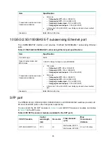
1/10BASE-T autosensing Ethernet port 

The LSWM2XGT2PM interface card provides 1/10BASE-T autosensing Ethernet ports. 

Table 20 1/10BASE-T autosensing Ethernet port specifications 

Item Specification 

Connector type


RJ-45 

Interface attributes 

1/10 Gbps, full duplex, MDI/MDI-X auto-sensing 

Max transmission distance


Category-6 UTP

—55 m (180.45 ft)  


Category-6 STP

—100 m (328.09 ft) 


Category-6 SFTP

—100 m (328.09 ft) 


Category-6 and above twisted pair

—100 m (328.09 ft) 

Transmission medium


Category-6 (or above) twisted pair cable 

Standards


IEEE 802.3an, 802.3ab 


10/100/1000BASE-T autosensing Ethernet port 

All the S5560X-EI switch models, except the S5560X-54F-EI switch, provide 10/100/1000BASE-T 
autosensing Ethernet ports. 

Table 21 10/100/1000BASE-T autosensing Ethernet port specifications 

Item Specification 

Connector type


RJ-45 

Interface attributes 


10 Mbps, half/full duplex 


100 Mbps, half/full duplex 


1000 Mbps, full duplex 

 MDI/MDI-X, 

auto-sensing 

Max transmission distance


100 m (328.08 ft) 

Transmission medium


Category-5 (or above) twisted pair cable 

Standards


IEEE 802.3i, 802.3u, 802.3ab 


5G/2.5G/1000BASE-T autosensing Ethernet port 

The LSWM2MGT8P interface card provides 5G/2.5G/1000BASE-T autosensing Ethernet ports. 

Table 22 5G/2.5G/1000BASE-T autosensing Ethernet port specifications 

Item Specification 

Connector type


RJ-45 

Port speed, duplex mode, 
MDIX mode 

1/2.5/5 Gbps, full duplex, auto-MDI/MDIX 

Содержание S5560X-EI Series

Страница 1: ...H3C S5560X EI Switch Series Installation Guide New H3C Technologies Co Ltd http www h3c com Document version 6W106 20191119...

Страница 2: ...respective owners Notice The information in this document is subject to change without notice All contents in this document including statements information and recommendations are believed to be acc...

Страница 3: ...syntax choices keywords or arguments that are optional x y Braces enclose a set of required syntax choices separated by vertical bars from which you select one x y Square brackets enclose a set of op...

Страница 4: ...s a Layer 2 or Layer 3 switch or a router that supports Layer 2 forwarding and other Layer 2 features Represents an access controller a unified wired WLAN module or the access controller engine on a u...

Страница 5: ...Documentation feedback You can e mail your comments about product documentation to info h3c com We appreciate your comments...

Страница 6: ...20 Installing a PSR360 56A PSR560 56D PSR720 56A PSR1110 56A power module 20 Removing a PSR360 56A PSR560 56D PSR720 56A PSR1110 56A power module 22 Connecting the power cord 23 Connecting the power c...

Страница 7: ...ds 62 Connecting cables to the copper ports on the interface cards 64 Appendix C Ports and LEDs 66 Ports 66 Console port 66 Management Ethernet port 66 USB port 66 1 10BASE T autosensing Ethernet port...

Страница 8: ...ersonnel Safety recommendations To avoid any equipment damage or bodily injury caused by improper use read the following safety recommendations before installation Note that the recommendations do not...

Страница 9: ...mperature and humidity in the equipment room as described in Appendix A Chassis views and technical specifications Lasting high relative humidity can cause poor insulation electricity leakage mechanic...

Страница 10: ...wire power receptacle with protection earth PE to filter interference from the power grid Keep the switch far away from radio transmitting stations radar stations and high frequency devices Use electr...

Страница 11: ...the switch CAUTION Keep the tamper proof seal on a mounting screw on the chassis cover intact and if you want to open the chassis contact H3C for permission Otherwise H3C shall not be liable for any...

Страница 12: ...n the circuit breakers Operating correctly Turn off the circuit breakers Resolve the problem With expansion slots Yes Yes No No Install expansion cards Operating correctly Yes No Resolve the problem E...

Страница 13: ...de Install the rear mounting brackets based on the rack depth If the rack depth is in the range of 429 to 595 mm 16 89 to 23 43 in orient the bracket with the wide flange inside the rack If the rack d...

Страница 14: ...0X 54C EI S5560X 30F EI S5560X 54F EI S5560X 34S EI S5560X 54S EI Provided N A S5560X 30C PWR EI S5560X 54C PWR EI Provided Provided Figure 4 Front mounting bracket 1 Screw hole for attaching the brac...

Страница 15: ...e Figure 6 and Figure 7 b Use M4 screws provided with the switch to attach the mounting bracket to the chassis c Repeat the proceeding two steps to attach the other mounting bracket to the chassis Fig...

Страница 16: ...with the cage nuts on the rack posts 5 The other person attaches the mounting brackets with M6 screws user supplied to the rack Figure 8 Mounting the switch in the rack front mounting brackets at the...

Страница 17: ...assis See Figure 10 2 Use M4 screws supplied with the switch to attach the mounting bracket to the chassis 3 Repeat the proceeding two steps to attach the other mounting bracket to the chassis 4 Unpac...

Страница 18: ...rack Mounting the switch in the rack 1 Wear an ESD wrist strap and make sure it makes good skin contact and is reliably grounded 2 Make sure the front mounting brackets and shoulder screws are secure...

Страница 19: ...the rear mounting brackets as shown in Figure 13 5 The other person attaches the front mounting brackets with M6 screws user supplied to the front rack posts Make sure the switch is installed securely...

Страница 20: ...safety at the site and minimize EMI susceptibility of the system You can ground the switch in one of the following ways depending on the grounding conditions available at the installation site Ground...

Страница 21: ...nnecting to the grounding strip 3 Attach a ring terminal to the grounding cable a Use a wire stripper to strip 5 mm 0 20 in of insulation off the end of the grounding cable b Slide the heat shrink tub...

Страница 22: ...ip 3 Attach the bended part of the grounding cable to the grounding post and use the hex nut to fasten the bended part to the post Figure 18 Connecting the grounding cable to the grounding strip 1 Gro...

Страница 23: ...iled fan tray is in position before the replacement If the ambient temperature is higher than 27 C 80 6 F replace the fan tray immediately If you power cycle the switch after a fan tray fails the swit...

Страница 24: ...tray IMPORTANT At the first login to the switch use the fan prefer direction command to set the airflow direction of the switch to be the same as the airflow direction of the fan tray If the fan tray...

Страница 25: ...y mode you can replace a power module without powering off the switch but you must strictly follow the installation and removal procedures in Figure 22 and Figure 23 to avoid any bodily injury or dama...

Страница 26: ...rget power module slot as follows a Remove the screws on the filler panel b Use a flathead screwdriver to remove the filler panel Figure 24 Removing the filler panel 3 Unpack the power module and veri...

Страница 27: ...removed power module in an antistatic bag or the power module package bag for future use 5 Install the filler panel to prevent dust and ensure good ventilation if no power module is installed in the s...

Страница 28: ...module with one hand and support its bottom with the other and slide the power module slowly along the guide rails into the slot until you hear that the latch of the power module clicks into the slot...

Страница 29: ...PSR720 56A power module 1 Wear an ESD wrist strap and make sure it makes good skin contact and is reliably grounded 2 Disconnect the power cord 3 Press the latch towards the handle and pull the power...

Страница 30: ...the PSR150 A1 PSR150 A2 PSR150 D1 48 VDC power source in the equipment room or an RPS RPS800 A or RPS1600 A Connecting the PSR150 D1 PSR560 56D PSR560 56D 48 VDC power source in the equipment room or...

Страница 31: ...t 2 in Figure 31 5 Connect the other end of the power cord to an AC power source Figure 30 Connecting the power cord for the built in AC power module 1 Figure 31 Connecting the power cord for the buil...

Страница 32: ...g a power cord for the built in DC power module Connecting the PSR150 A1 PSR150 A2 The power cord connection procedure is the same for the PSR150 A1 and PSR150 A2 power modules The following procedure...

Страница 33: ...n ESD wrist strap and make sure it makes good skin contact and is reliably grounded 2 Unpack the DC power cord correctly orient the connector at one end of the cable with the DC input power receptacle...

Страница 34: ...56A power module as an example To connect the PSR720 56A 1 Wear an ESD wrist strap and make sure it makes good skin contact and is reliably grounded 2 Plug the female connector end of the AC power co...

Страница 35: ...r For the expansion cards available for the switch see Appendix B FRUs and compatibility matrixes The installation and removal procedure is similar for expansion cards The following procedure uses the...

Страница 36: ...Figure 39 c Rotate in the ejector lever as shown by callout 3 in Figure 39 d Use a Phillips screwdriver to tighten the captive screws on the expansion card to secure it in the slot See callout 4 in F...

Страница 37: ...30 Figure 39 Installing an expansion card with an ejector lever LSWM2SP2PM Figure 40 Installing an expansion card without an ejector lever LSPM6FWD...

Страница 38: ...pull the expansion card out of the chassis along the guide rails 5 If you are not to install a new expansion card after removing the original one install a filler panel in the slot to prevent dust an...

Страница 39: ...onsole cable or a micro USB console cable Prepare these cables yourself or purchase them from H3C Figure 42 Connecting the serial console port to a PC Connecting the serial console cable A serial cons...

Страница 40: ...icro USB Type B connector at one end to connect to the micro USB console port of the switch and a standard USB Type A connector at the other end to connect to the USB port on the PC To connect to the...

Страница 41: ...34 Figure 44 Device Driver Installation Wizard 6 Click Continue Anyway if the following dialog box appears Figure 45 Software Installation 7 Click Finish...

Страница 42: ...the terminal emulator programs see the user guides for these programs The following are the required terminal settings Bits per second 9 600 Data bits 8 Parity None Stop bits 1 Flow control None Power...

Страница 43: ...ons differ with software versions For more information about Boot ROM menu options see the software matching release notes for the device After the startup completes you can access the CLI to configur...

Страница 44: ...geability IRF fabric setup flowchart Figure 47 IRF fabric setup flowchart To set up an IRF fabric Step Description 1 Plan IRF fabric setup Plan the installation site and IRF fabric setup parameters Pl...

Страница 45: ...lan the installation site depending on your network solution as follows Place all IRF member switches in one rack for centralized high density access Distribute the IRF member switches in different ra...

Страница 46: ...port to it When connecting two neighboring IRF member switches you must connect the physical ports of IRF port 1 on one switch to the physical ports of IRF port 2 on the other switch The S5560X EI sw...

Страница 47: ...g Ethernet ports SFP ports SFP28 ports QSFP ports Planning the cabling scheme The cables available for connecting two peer IRF physical ports vary by port type 1 10GBASE T autosensing Ethernet ports 5...

Страница 48: ...pair SFP SFP28 QSFP cables to connect the IRF member switches 9 switches in this example in a rack as shown in Figure 50 The switches in the ring topology see Figure 51 are in the same order as connec...

Страница 49: ...n the master switch higher member priority than any other switch Bind physical ports to IRF port 1 on one switch and to IRF port 2 on the other switch You perform IRF port binding before or after conn...

Страница 50: ...S5560X EI Switch Series Fundamentals Configuration Guide 4 Verify that you can manage all member switches as if they were one node 5 Display the running status of the IRF fabric by using the commands...

Страница 51: ...mperature of the switch is in the acceptable range and ensure good ventilation for the power module Overtemperature can cause the power module to stop working and enter the protection state 4 If the p...

Страница 52: ...ersists contact H3C Support Hot swappable power module failure Symptom S5560X EI switches except the S5560X 34S EI and S5560X 54S EI use hot swappable power modules To identify the operating status of...

Страница 53: ...e Installing removing a fan tray to replace the fan tray Configuration terminal display problems If the configuration environment setup is correct the configuration terminal displays booting informati...

Страница 54: ...47 Flow control None 2 If the problem persists contact H3C Support...

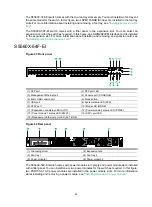
Страница 55: ...D PWR2 13 Power module 1 status LED PWR1 14 SFP port LED 15 Management Ethernet port LED ACT LINK 16 SFP port LED 17 SFP port Figure 54 Rear panel 1 Grounding screw 2 Fan tray 1 3 Expansion card 4 Fan...

Страница 56: ...ernet port 2 10 100 1000BASE T autosensing Ethernet port LED 3 Management Ethernet port 4 Console port CONSOLE 5 Micro USB console port 6 Mode button 7 USB port 8 System status LED SYS 9 SFP port 10 M...

Страница 57: ...BASE T autosensing Ethernet port 2 10 100 1000BASE T autosensing Ethernet port LED 3 Management Ethernet port 4 Console port CONSOLE 5 Micro USB console port 6 Mode button 7 USB port 8 System status L...

Страница 58: ...nsing Ethernet port 2 10 100 1000BASE T autosensing Ethernet port LED 3 Management Ethernet port 4 Console port CONSOLE 5 Micro USB console port 6 Mode button 7 USB port 8 System status LED SYS 9 SFP...

Страница 59: ...tosensing Ethernet port 4 10 100 1000BASE T autosensing Ethernet port LED 5 Management Ethernet port 6 Console port CONSOLE 7 Micro USB console port 8 Mode button 9 USB port 10 System status LED SYS 1...

Страница 60: ...re 63 Front panel 1 SFP port 2 SFP port LED 3 Management Ethernet port 4 Console port CONSOLE 5 Micro USB console port 6 Mode button 7 USB port 8 System status LED SYS 9 SFP port 10 Mode LED MODE 11 E...

Страница 61: ...talled in the expansion slot For more information about installing and removing an expansion card see Installing removing an expansion card S5560X 34S EI Figure 65 Front panel 1 10 100 1000BASE T auto...

Страница 62: ...P port 3 AC power receptacle 4 DC power receptacle 5 Grounding screw Technical specifications Table 10 Technical specifications for non PoE switch models 1 Item S5560X 30C EI S5560X 54C EI S5560X 30F...

Страница 63: ...DC input for the PSR150 D1 power module You can use a 48 VDC power source in the equipment room or an RPS RPS800 A or RPS1600 A Rated voltage range 48 VDC to 60 VDC Max voltage range 36 VDC to 72 VDC...

Страница 64: ...FP port 4 Each and its corresponding 10 100 1000BASE T port form a combo interface N A 10 100 1000BASE T autosensing Ethernet port 28 48 Input voltage AC input Rated voltage range 100 VAC to 240 VAC 5...

Страница 65: ...115 VAC to 240 VAC 50 Hz or 60 Hz Max voltage range 102 5 VAC to 264 VAC 47 Hz to 63 Hz DC input for the PSR560 56D power module You can use a 48 VDC power source in the equipment room or an RPS RPS16...

Страница 66: ...10 W 30 W 1560 W 30 W 1 PSR1110 56A and 1 PSR560 56D 810 W 30 W 1440 W 30 W 1 PSR1110 56A and 1 PSR360 56A 810 W 30 W 1200 W 30 W 2 PSR720 56A 810 W 30 W 1200 W 30 W 1 PSR720 56A and 1 PSR560 56D 810...

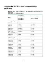
Страница 67: ...supported Supported PSR560 56D Not supported Supported PSR720 56A Not supported Supported PSR1110 56A Not supported Supported Hot swappable fan trays LSPM1FANSA Supported Supported LSPM1FANSB Supporte...

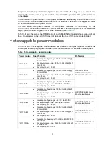
Страница 68: ...ower modules Power module Specifications Reference PSR150 A1 Rated input voltage range 100 VAC to 240 VAC 50 Hz or 60 Hz Max input voltage range 90 VAC to 264 VAC 47 Hz to 63 Hz Max output power 150 W...

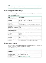
Страница 69: ...W Reference H3C LSPM1FANSA LSPM1FANSB Fan Trays User Guide LSPM1FANSB fan tray Dimensions 40 40 104 mm 1 57 1 57 4 09 in Fan speed 20000 R P M Max airflow 20 CFM Airflow direction Front to back from t...

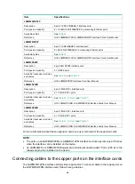
Страница 70: ...e T autosensing Ethernet ports 6 SFP fiber ports SFP ports 5S and 6S form combo interfaces with 10 100 1000Base T autosensing Ethernet ports 5T and 6T respectively Available transceiver modules and ca...

Страница 71: ...ty 2 1 10GE SFP ports Available transceiver modules and cables See Table 25 Table 26 and Table 27 Reference H3C LSWM2SP2PB LSWM2SP4PB Interface Cards User Manual LSWM2SP4PB Description 4 port 10GE SFP...

Страница 72: ...adjacent to one another on the device the peer ports on the distribution frame is preferably not adjacent for example If the device connects to one distribution frame connect port 1 on the device to...

Страница 73: ...for loading and debugging software or remote management Table 19 Management Ethernet port specifications Item Specification Connector type RJ 45 Connector quantity 1 Port transmission rate 10 100 1000...

Страница 74: ...ll the S5560X EI switch models except the S5560X 54F EI switch provide 10 100 1000BASE T autosensing Ethernet ports Table 21 10 100 1000BASE T autosensing Ethernet port specifications Item Specificati...

Страница 75: ...ansmission distance 10G mode Category 6 UTP 55 m 180 45 ft Category 6 STP 100 m 328 09 ft Category 6e twisted pair 100 m 328 09 ft 5G mode Category 5e UTP 55 m 180 45 ft Category 5e STP 100 m 328 09 f...

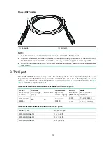
Страница 76: ...ransceiver module and cable Central wavelength nm Connector Cable Fiber type and diameter m Modal bandwidth MHz km Max transmission distance SFP copper transceiver module SFP GE T N A RJ 45 Twisted pa...

Страница 77: ...ransceiver modules on the S5560X 30C EI S5560X 30F EI and S5560X 54F EI switches separate these transceiver modules by other types of transceiver modules For example you can install SFP GE LH100 SM155...

Страница 78: ...25 2000 300 m 984 25 ft 500 82 m 269 03 ft 400 66 m 216 54 ft Multi mode 62 5 125 200 33 m 108 27 ft 160 26 m 85 30 ft SFP XG LX S M1310 1310 LC Single mode 9 125 N A 10 km 6 21 miles SFP XG LX S M131...

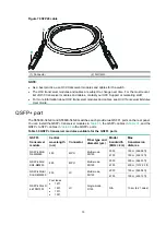
Страница 79: ...orts over a long distance use SFP28 transceiver modules and fibers To connect peer SFP28 ports over a short distance use SFP28 cables The SFP28 transceiver modules in Table 28 and SFP28 cables in Tabl...

Страница 80: ...l You can install the QSFP transceiver modules in Table 30 the QSFP cables in Table 31 and the QSFP to SFP cables in Table 32 in the QSFP ports Table 30 QSFP transceiver modules available for the QSFP...

Страница 81: ...M1QSTK2 5 m 16 40 ft Table 32 QSFP to SFP cables available for the QSFP ports QSFP to SFP cable Max transmission distance LSWM1QSTK3 1 m 3 28 ft LSWM1QSTK4 3 m 9 84 ft LSWM1QSTK5 5 m 16 40 ft Figure 7...

Страница 82: ...nsing Ethernet port Only one of these two ports can operate at a time LEDs System status LED The system status LED shows the operating state of the switch Table 33 System status LED description LED ma...

Страница 83: ...ports Flashing green 1 Hz available only for S5560X 30C PWR EI and S5560X 54C PWR EI switches The port status LEDs indicate the PoE power supply status of the ports Flashing yellow The port status LE...

Страница 84: ...port is not supplying power through PoE Flashing yellow IRF mode The S5560X 30C EI S5560X 54C EI S5560X 34S EI S5560X 54S EI S5560X 30C PWR EI and S5560X 54C PWR EI switches use the 10 100 1000BASE T...

Страница 85: ...de the SFP port LEDs are off SFP port LED Table 39 SFP port LED description Mode LED status SFP port LED status Description Steady green rate mode Steady green A link is present on the port and the po...

Страница 86: ...ing and receiving data at half duplex mode Off No link is present on the port Flashing yellow IRF mode Off When the Mode LED is flashing yellow IRF mode the port LEDs are off Management Ethernet port...

Страница 87: ...LED and an output status LED For more information about the LEDs see the manuals for the power modules Fan tray status LED on the fan tray The LSPM1FANSA and LSPM1FANSB fan trays each have a fan tray...

Страница 88: ...le fan trays They provide airflow from the port side to the power module side or from power module side to the port side by using different types of fan trays You must install two fan trays of the sam...

Страница 89: ...82 Figure 74 Airflow through the switch with hot swappable fan trays S5560X 54C EI...

Отзывы: