background image


11 

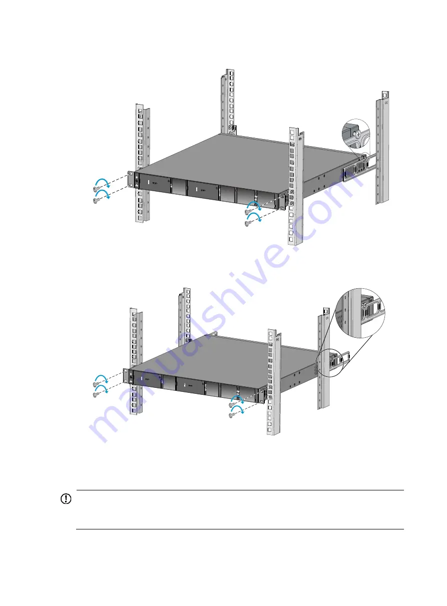
Figure 11


Mounting the switch in the rack (rear mounting brackets forward-oriented) 


Figure 12


Mounting the switch in the rack (rear mounting brackets backward-oriented) 


Mounting the switch on a workbench 


IMPORTANT: 


Ensure good ventilation and 10 cm (3.9 in) of clearance around the chassis for heat dissipation. 


Avoid placing heavy objects on the switch. 


To mount the switch on a workbench: 

Содержание S5560-HI Series

Страница 1: ...H3C S5560 HI Switch Series Installation Guide Hangzhou H3C Technologies Co Ltd http www h3c com Document version 6W101 20160520...

Страница 2: ...d All other trademarks that may be mentioned in this manual are the property of their respective owners Notice The information in this document is subject to change without notice Every effort has bee...

Страница 3: ...and keywords that you enter literally as shown Italic Italic text represents arguments that you replace with actual values Square brackets enclose syntax choices keywords or arguments that are option...

Страница 4: ...ormation NOTE An alert that contains additional or supplementary information TIP An alert that provides helpful information Network topology icons Represents a generic network device such as a router...

Страница 5: ...e appearance specifications and installation and removal of hot swappable fan trays Power modules user manual Describes the appearance specifications and installation and removal of hot swappable powe...

Страница 6: ...ick the following links to obtain different categories of product documentation Technical Documents Provides hardware installation software upgrading and software feature configuration and maintenance...

Страница 7: ...ving LSVM1AC300 and LSVM1DC300 power modules 18 Installing removing PSR360 56A PSR720 56A and PSR1110 56A power modules 20 Connecting the power cord 23 Connecting the LSVM1AC300 power module 23 Connec...

Страница 8: ...6 Connecting cables to the LSWM2XGT2PM LSWM2XGT8PM interface card 57 Appendix C Ports and LEDs 58 Ports 58 Console port 58 Management Ethernet port 58 USB port 58 10 100 1000BASE T autosensing Etherne...

Страница 9: ...ch free of obstruction Connect the yellow green protection grounding cable before power on Make sure the operating voltage is in the required range To avoid electrical shocks do not open the chassis w...

Страница 10: ...requirements of different switch models see Technical specifications Cleanliness Dust buildup on the chassis might result in electrostatic adsorption which causes poor contact of metal components and...

Страница 11: ...switch far away from radio transmitting stations radar stations and high frequency devices Use electromagnetic shielding for example shielded interface cables when necessary Laser safety WARNING Do n...

Страница 12: ...the switch CAUTION Keep the tamper proof seal on a mounting screw on the chassis cover intact and if you want to open the chassis contact H3C for permission Otherwise H3C shall not be liable for any...

Страница 13: ...5 Figure 1 Hardware installation flow...

Страница 14: ...forward If the rack depth is in the range of 274 to 440 mm 10 79 to 17 32 in and the distance from the rear rack posts to the inner surface of the cabinet door is longer than 153 mm 6 02 in orient th...

Страница 15: ...ou can only attach the front mounting brackets to the middle mounting position on the switch To install the switch in a 19 inch rack by using the front mounting brackets 1 Wear an ESD wrist strap and...

Страница 16: ...compatible with the cage nuts to attach the switch to the front rack posts Figure 7 Mounting the switch in the rack In this example the power side faces outwards Rack mounting by using the front and...

Страница 17: ...d Attach the load bearing screw to one of the two installation positions as red marked in Figure 8 e Repeat the proceeding step to attach the other load bearing screw to the chassis Figure 8 Attaching...

Страница 18: ...hand and pushes the chassis into the rack gently Make sure the load bearing screws closely contact with the upper edges of the rear mounting brackets as shown in Figure 11 and Figure 12 c The other p...

Страница 19: ...12 Mounting the switch in the rack rear mounting brackets backward oriented Mounting the switch on a workbench IMPORTANT Ensure good ventilation and 10 cm 3 9 in of clearance around the chassis for he...

Страница 20: ...ways depending on the grounding conditions available at the installation site Grounding the switch with a grounding strip Grounding the switch with a grounding conductor buried in the earth ground Gro...

Страница 21: ...a Use a wire stripper to strip 5 mm 0 20 in of insulation off the end of the grounding cable b Slide the heat shrink tubing onto the cable and insert the bare metal part into the end of the ring termi...

Страница 22: ...tube into the earth ground to serve as a grounding conductor The dimensions of the angle iron must be a minimum of 50 50 5 mm 1 97 1 97 0 20 in The steel tube must be zinc coated and its wall thicknes...

Страница 23: ...power cord is securely connected to the power outlet NOTE If the ground contact in the power outlet is not connected to the ground report the problem and reconstruct the grounding system Figure 17 Gro...

Страница 24: ...h empty fan tray slots Choose the fan tray models based on the ventilation requirement of the site The air flow direction varies by fan tray model The LSWM1FANSCE has a blue handle and provides power...

Страница 25: ...ctors require maintenance from maintenance engineers Do not disassemble the faulty fan trays To remove a fan tray 1 Wear an ESD wrist strap and make sure it makes good skin contact and is reliably gro...

Страница 26: ...le Installing a power module 1 Wear an ESD wrist strap and make sure it makes good skin contact and is reliably grounded 2 Unpack the power module and verify that the power module model is correct Kee...

Страница 27: ...r module incorrectly you cannot insert the power module into the slot To prevent damage to the power module or the connectors on the backplane insert the power module gently If you encounter a hard re...

Страница 28: ...uture use 5 If you are not to install a power module install the filler panel in the slot to prevent dust and ensure good ventilation Installing removing PSR360 56A PSR720 56A and PSR1110 56A power mo...

Страница 29: ...rails into the slot until the power module makes firm contact with the backplane connectors When the power module is completely inserted into the slot you can hear that the latch of the power module...

Страница 30: ...contact and is reliably grounded 2 Turn off the circuit breaker at the power input end and remove the power cord 3 As shown in Figure 29 press the latch towards the handle and pull the power module pa...

Страница 31: ...n procedure reference LSVM1AC300 AC input Connecting the LSVM1AC300 power module LSVM1DC300 48 VDC input Connecting the LSVM1DC300 power module PSR360 56A PSR720 56A PSR1110 56A AC input Connecting th...

Страница 32: ...e tie to secure the AC power cord to the handle on the power module Figure 31 Securing the AC power cord with a cable tie 1 Figure 32 Securing the AC power cord with a cable tie 2 4 Connect the other...

Страница 33: ...e power module 4 Connect the two wires at the other end of the power cord to a 48 VDC power source Figure 33 Connecting a DC power cord to the power module Connecting the PSR360 56A PSR720 56A PSR1110...

Страница 34: ...T8PM without an ejector lever interface cards as examples to describe the procedures of installing and removing an expansion card Installing an expansion card 1 Wear an ESD wrist strap and make sure i...

Страница 35: ...the ejector lever as shown by callout 3 in Figure 36 Skip this step if the expansion card does not have an ejector lever 7 Tighten the captive screws with a Phillips screwdriver to secure the expansio...

Страница 36: ...not have an ejector lever 4 Gently pull the expansion card along the guide rails until it completely comes out of the switch chassis If you are not to install a new card install the filler panel in th...

Страница 37: ...switch You can prepare the cable yourself or purchase one from H3C Figure 39 Connecting the console port to a terminal Connecting the console cable A console cable is an 8 core shielded cable with a c...

Страница 38: ...o the mini USB console port of the switch and a standard USB Type A connector at the other end to connect to the USB port on the configuration terminal To connect to the configuration terminal through...

Страница 39: ...31 Figure 41 Device Driver Installation Wizard 6 Click Continue Anyway if the following dialog box appears Figure 42 Software Installation 7 Click Finish...

Страница 40: ...minal emulator programs see the user guides for these programs The following are the required terminal settings Bits per second 9 600 Data bits 8 Parity None Stop bits 1 Flow control None Powering on...

Страница 41: ...ions differ with software versions For more information about Boot ROM menu options see the software matching release notes for the device After the startup completes you can access the CLI to configu...

Страница 42: ...lity and manageability IRF fabric setup flowchart Figure 44 IRF fabric setup flowchart To set up an IRF fabric Step Description 1 Plan IRF fabric setup Plan the installation site and IRF fabric setup...

Страница 43: ...an IRF fabric equals the total switching capacities of all member switches Plan the installation site depending on your network solution as follows Place all IRF member switches in one rack for centra...

Страница 44: ...nd a minimum of one physical port to it When connecting two neighboring IRF member switches you must connect the physical ports of IRF port 1 on one switch to the physical ports of IRF port 2 on the o...

Страница 45: ...on the rear panel Planning the cabling scheme Use twisted pair SFP QSFP cables or SFP QSFP transceiver modules and fibers to connect the IRF member switches If the IRF member switches are far away fr...

Страница 46: ...38 Figure 47 Connecting the switches in one rack 1 2 3 4 5 6 7 8 9...

Страница 47: ...port bindings Follow these guidelines when you configure the switches Assign the master switch higher member priority than any other switch When connecting two neighboring IRF member switches you mus...

Страница 48: ...e network management station See H3C S5560 HI Switch Series Fundamentals Configuration Guide 4 Verify that you can manage all member switches as if they were one node 5 Display the running status of t...

Страница 49: ...switch is in an acceptable range and the power module has good ventilation 4 If the problem persists contact H3C Support To replace a power module see Installing removing a power module Fan tray failu...

Страница 50: ...on To resolve the problem 1 Verify that the power module is supplying power to the switch 2 Verify that the console cable is correctly connected 3 Verify that the console cable does not have any probl...

Страница 51: ...LED 3 Management Ethernet port 4 Management Ethernet port LED ACT LINK 5 Serial console port 6 Mini USB console port 7 Port mode LED MODE 8 USB port 9 Port LED mode switching button 10 System status L...

Страница 52: ...ower module see Installing removing a power module The S5560 32C HI switch comes with the two fan tray slots empty You must install two fan trays of the same model for the switch In Figure 51 two LSWM...

Страница 53: ...PWR2 14 Power module slot 1 LED PWR1 15 SFP port LED 16 SFP port Figure 53 Rear panel 1 Grounding screw 2 Expansion card 1 3 Fan tray 1 4 Expansion card 2 5 Fan tray 2 6 Power module 1 7 Power module...

Страница 54: ...ure 53 two LSWM2QP2P interface cards are installed in the expansion slots For more information about installing and removing an expansion card see Installing removing an expansion card S5560 38C HI XG...

Страница 55: ...power module see Installing removing a power module The S5560 38C HI XG switch comes with the two fan tray slots empty You must install two fan trays of the same model for the switch In Figure 55 two...

Страница 56: ...module slot 1 LED PWR1 15 SFP port LED 16 SFP port Figure 57 Rear panel 1 Grounding screw 2 Expansion card 1 3 Fan tray 1 4 Expansion card 2 5 Fan tray 2 6 Power module 1 7 Power module 2 The S5560 56...

Страница 57: ...For more information about installing and removing an expansion card see Installing removing an expansion card S5560 56C PWR HI Figure 58 Front panel 1 10 100 1000BASE T autosensing Ethernet port 2 1...

Страница 58: ...specifications for non PoE switch models Item S5560 32C HI S5560 38C HI XG S5560 56C HI S5560 56F HI Dimensions H W D 43 6 440 460 mm 1 72 17 32 18 11 in 43 6 440 460 mm 1 72 17 32 18 11 in 43 6 440 4...

Страница 59: ...0 1 GB4943 Melting current of power module fuse AC input 6 3 A 250 V DC input 20 A 125 V Operating temperature 0 C to 45 C 32 F to 113 F Relative humidity 5 to 95 noncondensing Fire resistance complia...

Страница 60: ...43 Melting current of power module fuse PSR360 56A 6 3 A 250 V PSR720 56A PSR1 1 10 56A 15 A 250 V Operating temperature 0 C to 45 C 32 F to 113 F Relative humidity 5 to 95 noncondensing Fire resistan...

Страница 61: ...GT2PM Yes Yes Yes LSWM2SP8P Yes No Yes LSWM2XGT8PM Yes No Yes LSPM6FWD Yes Yes Yes You can install one power module two power modules of the same model for redundancy or a mix of an AC power module an...

Страница 62: ...nge 100 VAC to 240 VAC 50 Hz or 60 Hz Maximum input voltage range 90 VAC to 264 VAC 47 Hz or 63 Hz Maximum output power 360 W Reference H3C PSR360 56A Power Module User Manual PSR720 56A Rated input v...

Страница 63: ...quantity 2 40 Gbps QSFP fiber port Available transceiver modules and cables See Table 23 Table 24 and Table 25 LSWM2SP8PM and LSWM2SP8P Product description 8 Port 10G SFP Plus Interface Card For more...

Страница 64: ...ansion slot 2 supports the LSWM2XGT8PM LSWM2SP8P and LSWM2SP8PM interface cards If you install the LSWM2QP2P interface card in expansion slot 2 you can split a QSFP port on the card into four SFP port...

Страница 65: ...0 m 65 62 ft Separate power cords and twisted pair cables at and around the distribution frame For ports adjacent to one another on the device the peer ports on the distribution frame is preferably no...

Страница 66: ...tion program Management Ethernet port The switch provides a management Ethernet port on the front panel You can connect this port to a PC or management station for loading and debugging software or re...

Страница 67: ...g Ethernet port The LSWM2XGT2PM and LSWM2XGT8PM interface cards provide 1 10GBASE T autosensing Ethernet ports Table 18 1 10GBASE T autosensing Ethernet port specifications Item Specification Connecto...

Страница 68: ...10 1310 LC Single mode 9 125 N A 40 km 24 86 miles SFP GE LH40 SM15 50 1550 LC Single mode 9 125 N A 40 km 24 86 miles SFP GE LH70 SM15 50 1550 LC Single mode 9 125 N A 70 km 43 50 miles SFP GE LH100...

Страница 69: ...ports Cable description Cable length LSWM1STK 0 65 m 2 13 ft LSWM2STK 1 2 m 3 94 ft LSWM3STK 3 m 9 84 ft LSTM1STK 5 m 16 40 ft Figure 60 SFP cable 1 Connector 2 Pull latch NOTE As a best practice use...

Страница 70: ...s As a best practice use only H3C SFP transceiver modules The SFP transceiver modules available for the switch are subject to change over time For the most up to date list of SFP transceiver modules c...

Страница 71: ...les available for the QSFP ports QSFP cable Max transmission distance LSWM1QSTK0 1 m 3 28 ft LSWM1QSTK1 3 m 9 84 ft LSWM1QSTK2 5 m 16 40 ft Table 25 QSFP to 4 x SFP cables available for the QSFP ports...

Страница 72: ...to connect a QSFP port to four SFP ports The QSFP transceiver module and SFP transceiver modules to be connected must be the same in specifications including central wavelength and fiber type For mor...

Страница 73: ...s installed in power module slot 2 Port mode LED To show more information about the switch through the port status LEDs the switch provides a port mode LED The port mode LED indicates the types of inf...

Страница 74: ...ellow 1 Hz IRF mode Steady green The port status LEDs indicate the IRF member ID of the switch For example if the LEDs for ports 1 to 5 are steady green the IRF member ID of the switch is 5 Off The po...

Страница 75: ...port Off No transceiver module is installed or no link is present on the port Management Ethernet port LED The switch provides an ACT LINK LED to indicate the operating state of the management Etherne...

Страница 76: ...output status LED on power modules Each power module has a power module LED to indicate the input and output status of the power module For more information about the LEDs see the user manuals for th...

Страница 77: ...fan trays When the LSWM1FANSCE fan tray is used ambient air flows in through the air vents in the fan tray and power module panels circulates through the chassis and the power modules and exhausts th...

Страница 78: ...56C PWR HI switch uses fixed fan trays Ambient air flows in from the air vents in the port side panel circulates through the chassis and power modules and exhausts through the air vents in the power...

Страница 79: ...bility matrixes 53 configuring IRF basic settings 39 switch 29 troubleshooting configuration terminal problems 42 verify the IRF fabric setup 40 41 connecting console cable 29 first time switch access...

Страница 80: ...oting 41 installation 16 16 removal 16 17 status LED 68 technical specifications 55 fiber laser safety recommendations 3 field replacement unit See FRU flow control parameter 32 flowchart of IRF fabri...

Страница 81: ...ports 37 installing EMI prevention 2 examining installation site 1 expansion card 26 26 fan tray 16 16 front and rear mounting bracket kit 8 front mounting bracket kit 7 IRF fabric installation site p...

Страница 82: ...member switch physical ports 37 planning IRF cabling scheme 37 37 IRF connections 36 IRF member IDs 35 IRF topology 36 port connecting IRF physical ports 39 identifying IRF member switch physical por...

Страница 83: ...roubleshooting no terminal display 42 troubleshooting power module failure 41 PSR1 1 10 56A connecting 25 installation 20 removal 20 PSR360 56A connecting 25 installation 20 removal 20 PSR720 56A conn...

Страница 84: ...administration troubleshooting configuration terminal problems 42 troubleshooting fan tray failure 41 troubleshooting power module failure 41 system status LED 64 T technical specifications 50 10 100...

Страница 85: ...77 U USB port 58 V verify the IRF fabric setup 40 41 verifying IRF fabric setup 40 41 switch installation 28 VT100 32 W workbench mounting switch 1 1...

Отзывы: