background image

Operation Manual – MSTP 
H3C S3100-52P Ethernet Switch 

Chapter 1  MSTP Configuration


1-27 

mechanism disables the switches that are beyond the maximum hop count from 
participating in spanning tree calculation, and thus limits the size of an MST region. 

With such a mechanism, the maximum hop count configured on the switch operating as 
the root bridge of the CIST or an MSTI in an MST region becomes the network diameter 
of the spanning tree, which limits the size of the spanning tree in the current MST region. 
The switches that are not root bridges in the MST region adopt the maximum hop 
settings of their root bridges. 

I. Configuration procedure 

Follow these steps to configure the maximum hop count for an MST region: 

To do... 

Use the command... 

Remarks 

Enter system view 

system-view 

— 

Configure the maximum 
hop count of the MST 
region 

stp max-hops


hops


Required 
By default, the maximum 
hop count of an MST 
region is 20.


The bigger the maximum hop count, the larger the MST region is. Note that only the 
maximum hop settings on the switch operating as a region root can limit the size of the 
MST region. 

II. Configuration example 

# Configure the maximum hop count of the MST region to be 30. 

<Sysname> system-view 

[Sysname] stp max-hops 30 

1.3.8  Configuring the Network Diameter of the Switched Network 

In a switched network, any two switches can communicate with each other through a 
specific path made up of multiple switches. The network diameter of a network is 
measured by the number of switches; it equals the number of the switches on the 
longest path (that is, the path containing the maximum number of switches). 

I. Configuration procedure 

Follow these steps to configure the network diameter of the switched network: 

To do... 

Use the command... 

Remarks 

Enter system view 

system-view 

— 

Configure the network 
diameter of the switched 
network 

stp bridge-diameter


bridgenumber


Required 
The default network 
diameter of a network is 7.

Содержание S3100-52P

Страница 1: ...1 27 1 3 9 Configuring the MSTP Time related Parameters 1 28 1 3 10 Configuring the Timeout Time Factor 1 29 1 3 11 Configuring the Maximum Transmitting Rate on the Current Port 1 30 1 3 12 Configuri...

Страница 2: ...uction 1 48 1 7 2 Configuring Digest Snooping 1 48 1 8 Configuring Rapid Transition 1 50 1 8 1 Introduction 1 50 1 8 2 Configuring Rapid Transition 1 51 1 9 Configuring VLAN VPN Tunnel 1 53 1 9 1 Intr...

Страница 3: ...n z Displaying STP maintenance Refer to Displaying and Maintaining MSTP z Sending trap messages conforming to 802 1d standard Refer to Enabling Trap Messages Conforming to 802 1d Standard 1 1 STP Over...

Страница 4: ...e network and the root bridge can change alone with changes of the network topology Therefore the root bridge is not fixed Upon network convergence the root bridge generates and sends out configuratio...

Страница 5: ...evice A forwards BPDUs to Device B through AP1 the designated bridge for Device B is Device A and the designated port is the port AP1 on Device A z Two devices are connected to the LAN Device B and De...

Страница 6: ...lifetime for the configuration BPDUs to be kept in a switch z Hello time configuration BPDU interval z Forward delay forward delay of the port Note For the convenience of description the description...

Страница 7: ...n BPDU that has the lowest root bridge ID has the highest priority z If all configuration BPDUs have the same root bridge ID they will be compared for their root path costs If the root path cost in a...

Страница 8: ...sed on the comparison result z If the calculated configuration BPDU is superior this port will serve as the designated port and the configuration BPDU on the port will be replaced with the calculated...

Страница 9: ...The following table shows the initial state of each device Table 1 4 Initial state of each device Device Port name BPDU of port AP1 0 0 0 AP1 Device A AP2 0 0 0 AP2 BP1 1 0 1 BP1 Device B BP2 1 0 1 BP...

Страница 10: ...e configuration BPDU of Device A 0 0 0 AP1 Device B finds that the received configuration BPDU is superior to the configuration BPDU of the local port 1 0 1 BP1 and updates the configuration BPDU of B...

Страница 11: ...Designated port CP2 0 10 2 CP2 z Next port CP2 receives the updated configuration BPDU of Device B 0 5 1 BP2 Because the received configuration BPDU is superior to its old one Device C launches a BPD...

Страница 12: ...to time the configuration BPDU while it sends out this configuration BPDU through the designated port z If the configuration BPDU received on the designated port has a lower priority than the configur...

Страница 13: ...propagated throughout the entire network z Hello time the interval for sending hello packets Hello packets are used to check link state A switch sends hello packets to its neighboring devices at a reg...

Страница 14: ...tree II Features of MSTP The multiple spanning tree protocol MSTP overcomes the shortcomings of STP and RSTP In addition to support for rapid network convergence it also allows data flows of different...

Страница 15: ...o these switches These switches have the same region name the same VLAN to MSTI mapping configuration and the same MSTP revision level A switched network can contain multiple MST regions You can group...

Страница 16: ...k that connects all MST regions in the network If you regard each MST region in the network as a switch then the CST is the spanning tree generated by STP or RSTP running on the switches VI CIST A CIS...

Страница 17: ...or master port z A backup port is the secondary port of a designated port and is used for rapid transition With the designated port being blocked the backup port becomes the new designated port fast a...

Страница 18: ...ding state Ports in this state can forward user packets and receive send BPDU packets z Learning state Ports in this state can receive send BPDU packets but do not forward user packets z Discarding st...

Страница 19: ...n it as a root with the root path cost being 0 the ID of the designated bridge being that of the switch and the designated port being itself 1 Each switch sends out its configuration BPDUs and operate...

Страница 20: ...n compares the calculated configuration BPDU with the original configuration BPDU received from the corresponding port on another switch If the latter takes precedence over the former the switch block...

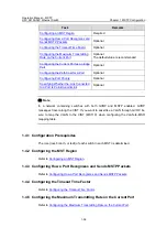
Страница 21: ...How a Port Recognizes and Sends MSTP Packets Optional Configuring the MSTP Operation Mode Optional Configuring the Maximum Hop Count of an MST Region Optional Configuring the Network Diameter of the...

Страница 22: ...LAN to MSTI mapping table for the MST region vlan mapping modulo modulo Required Both commands can be used to configure VLAN to MSTI mapping tables By default all VLANs in an MST region are mapped to...

Страница 23: ...tor which is 0 by default and cannot be configured MST region name VLAN to MSTI mapping table and revision level z The H3C series support only the MST region name VLAN to MSTI mapping table and revisi...

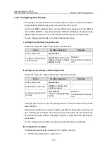
Страница 24: ...Enter system view system view Specify the current switch as the secondary root bridge of a specified spanning tree stp instance instance id root secondary bridge diameter bridgenumber hello time cent...

Страница 25: ...o configure the current switch as the root bridge by setting the priority of the switch to 0 Note that once a switch is configured as the root bridge or a secondary root bridge its priority cannot be...

Страница 26: ...kets in legacy format z 802 1s mode Ports in this mode recognize send packets in dot1s format A port acts as follows according to the format of MSTP packets forwarded by a peer switch or router When a...

Страница 27: ...format of the packets received Table 1 7 Follow these steps to configure how a port recognizes and sends MSTP packets in Ethernet port view To do Use the command Remarks Enter system view system view...

Страница 28: ...ghboring devices In this case the switch is MSTP capable I Configuration procedure Follow these steps to configure the MSTP operation mode To do Use the command Remarks Enter system view system view C...

Страница 29: ...By default the maximum hop count of an MST region is 20 The bigger the maximum hop count the larger the MST region is Note that only the maximum hop settings on the switch operating as a region root...

Страница 30: ...me related parameters exist forward delay hello time and max age You can configure the three parameters to control the process of spanning tree calculation I Configuration procedure Follow these steps...

Страница 31: ...nable to be detected in time which prevents spanning trees being recalculated in time and makes the network less adaptive The default value is recommended As for the configuration of the three time re...

Страница 32: ...nfigure the timeout time factor To do Use the command Remarks Enter system view system view Configure the timeout time factor for the switch stp timer factor number Required The timeout time factor de...

Страница 33: ...ts on a switch defaults to 10 As the maximum transmitting rate parameter determines the number of the configuration BPDUs transmitted in each hello time set it to a proper value to prevent MSTP from o...

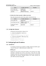
Страница 34: ...port view Follow these steps to configure a port as an edge port in Ethernet port view To do Use the command Remarks Enter system view system view Enter Ethernet port view interface interface type int...

Страница 35: ...ne of the following two ways I Specify whether the link connected to a port is point to point link in system view Follow these steps to specify whether the link connected to a port is point to point l...

Страница 36: ...nfigure the link connected to Ethernet 1 0 1 as a point to point link 1 Perform this configuration in system view Sysname system view Sysname stp interface Ethernet 1 0 1 point to point force true 2 P...

Страница 37: ...g tree calculation this operation saves CPU resources of the switch Other MSTP related settings can take effect only after MSTP is enabled on the switch II Configuration example Enable MSTP on the swi...

Страница 38: ...e In a network containing switches with both GVRP and MSTP enabled GVRP messages travel along the CIST If you want to advertise a VLAN through GVRP be sure to map the VLAN to the CIST MSTI 0 when conf...

Страница 39: ...ng standards z dot1d 1998 Adopts the IEEE 802 1D 1998 standard to calculate the default path costs of ports z dot1t Adopts the IEEE 802 1t standard to calculate the default path costs of ports z legac...

Страница 40: ...less than that of the port operating in half duplex mode When calculating the path cost of an aggregated link the 802 1D 1998 standard does not take the number of the ports on the aggregated link int...

Страница 41: ...A Configure the path cost of Ethernet 1 0 1 in MSTI 1 to be 2 000 1 Perform this configuration in system view Sysname system view Sysname stp interface Ethernet 1 0 1 instance 1 cost 2000 2 Perform t...

Страница 42: ...ce id port priority priority Required The default port priority is 128 II Configure port priority in Ethernet port view Follow these steps to configure port priority in Ethernet port view To do Use th...

Страница 43: ...the STP enabled downstream switch is then replaced by an MSTP enabled switch the port cannot automatically transit to the MSTP mode It remains in the STP compatible mode In this case you can force the...

Страница 44: ...form this configuration in system view Sysname system view Sysname stp interface Ethernet 1 0 1 mcheck 2 Perform this configuration in Ethernet port view Sysname system view Sysname interface Ethernet...

Страница 45: ...uard function Ports with this function enabled can only be kept as designated ports in all MSTIs When a port of this type receives configuration BPDUs with higher priorities it turns to the discarding...

Страница 46: ...ved within a period is less than the maximum times the switch performs a removing operation upon receiving a TC BPDU After the number of the TC BPDUs received reaches the maximum times the switch stop...

Страница 47: ...s not applicable to these ports even if you enable the BPDU guard function and specify these ports to be MSTP edge ports 1 6 4 Configuring Root Guard I Configuration procedure Follow these steps to co...

Страница 48: ...iew Sysname interface Ethernet 1 0 1 Sysname Ethernet1 0 1 stp root protection 1 6 5 Configuring Loop Guard I Configuration procedure Follow these steps to configure loop guard To do Use the command R...

Страница 49: ...old number Optional III Configuration example Enable the TC BPDU attack guard function Sysname system view Sysname stp tc protection enable Set the maximum times for the switch to remove the MAC addre...

Страница 50: ...d to another manufacturer s switch that has the same MST region related configuration as its own but adopts a proprietary spanning tree protocol you can enable digest snooping on the port Then the S31...

Страница 51: ...nly when your switch is connected to another manufacturer s switches adopting proprietary spanning tree protocols z To enable the digest snooping feature successfully you must first enable it on all t...

Страница 52: ...t from the downstream switch The difference between RSTP and MSTP are z For MSTP the upstream switch sends agreement packets to the downstream switch and the downstream switch sends agreement packets...

Страница 53: ...as the upstream switch connects with a H3C series switch running MSTP the upstream designated port fails to change its state rapidly The rapid transition feature is developed to resolve this problem W...

Страница 54: ...eps to configure the rapid transition feature in system view To do Use the command Remarks Enter system view system view Enable the rapid transition feature stp interface interface type interface numb...

Страница 55: ...endent of those of the service provider network As shown in Figure 1 9 the upper part is the service provider network and the lower part comprises the customer networks The service provider network co...

Страница 56: ...led devices only z To enable the VLAN VPN tunnel function make sure the links between service provider networks are trunk links 1 10 STP Maintenance Configuration 1 10 1 Introduction In a large scale...

Страница 57: ...itch sends trap messages conforming to 802 1d standard to the network management device in the following two cases z The switch becomes the root bridge of an instance z Network topology changes are de...

Страница 58: ...Available in any view Clear statistics about MSTP reset stp interface interface list Available in user view 1 13 MSTP Configuration Example I Network requirements Implement MSTP in the network shown...

Страница 59: ...n configuration Configure the region name VLAN to MSTI mapping table and revision level for the MST region Sysname mst region region name example Sysname mst region instance 1 vlan 10 Sysname mst regi...

Страница 60: ...region configuration Configure the MST region Sysname mst region region name example Sysname mst region instance 1 vlan 10 Sysname mst region instance 3 vlan 30 Sysname mst region instance 4 vlan 40 S...

Страница 61: ...The VLAN VPN tunnel function is enabled in system view thus implementing transparent transmission between the customer networks and the service provider network II Network diagram Figure 1 11 Network...

Страница 62: ...Ethernet 1 0 2 Sysname Ethernet1 0 2 port link type trunk Add the trunk port to all VLANs Sysname Ethernet1 0 2 port trunk permit vlan all 4 Configure Switch D Enable MSTP Sysname system view Sysname...

Отзывы: