


35
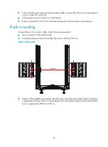
Figure 33
Installing the switch in a standard 19-inch rack
NOTE:
If the screw holes on the mounting brackets cannot align with the cage nuts on the rack, verify that the
bottom edge of the slide rail aligns with the middle of the narrowest metal area between mounting holes
and that the cage nuts are installed in the correct holes.
Verifying the installation
After the installation is completed, check the installation against the following checklist. Make sure all
check results are positive.
Table 12
Installation checklist
Item
Result
Remarks
Yes
No
The mounting brackets are firmly attached to the switch.
The switch is sturdy and installed in the right position.
The mounting brackets on the switch are firmly attached to the rack.
Installing the switch on a workbench
You can install the switch on a clean, sturdy workbench or on the floor.
Installation preparation
Before placing the switch on a workbench or on the floor, confirm the following preparations:
Содержание S12500 Series
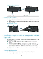
Страница 40: ...30 Figure 28 Installing an upper expansion cable management bracket 1 2 3 4 5 6 7...
Страница 109: ...99 Figure 74 Replacing a card for the S12504 A Card to be removed B Card to be installed...
Страница 149: ...139 Figure 85 Loopback operation on an optical transceiver...
Страница 164: ...154 Figure 100 Example of a device label...
Страница 167: ...157 Figure 104 Network cable management...


