


2-25
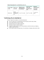
Table2-5 Requirements for a suitable DC power cord
Power supply
model
Power cord
connector
Minimum cross
sectional area of
the conductor
Cross sectional
area of the
provided power
cord
Maximum
cross sectional
area of the
conductor
PSR450-12D
Use the
connector of the
provided power
cord
2.1 mm
2
or 14 AWG
3.3
mm
2
or 12 AWG
3.3
mm
2
or 12
AWG
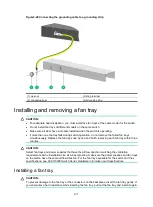
Verifying the installation
After you complete the installation, verify the following items:
•
There is enough space for heat dissipation around the switch, and the rack is stable.
•
The grounding cable is securely connected.
•
The power source is as required by the switch.
•
The power cords are correctly connected.
•
If part of the network cable for a port is routed outdoors, verify that a network port lightning
protector is used for the port.
•
All the interface cables are cabled indoors. The switch does not support outdoor cable routing.