background image


REMOTE CONTROL CONFIG 

167 

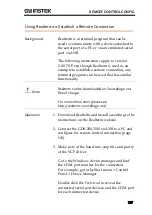
Using Realterm to Establish a Remote Connection 


Background   

Realterm is a terminal program that can be 
used to communicate with a device attached to 
the serial port of a PC or via an emulated serial 
port via USB.  

The following instructions apply to version 
2.0.0.70. Even though Realterm is used as an 
example to establish a remote connection, any 
terminal program can be used that has similar 
functionality.  

 Note 

Realterm can be downloaded on Sourceforge.net 
free of charge.  

For more information please see 
http://realterm.sourceforge.net/ 

Operation 

1.


Download Realterm and install according to the 
instructions on the Realterm website. 


2.


Connect the GDS-200/300 via USB to a PC and 
configure for remote control connection (page 
165). 


3.


Make note of the baud rate, stop bits and parity 
of the VCP driver. 


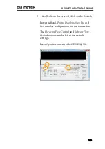
Go to the Windows device manager and find 
the COM port number for the connection.  
For example, go to the Start menu > Control 
Panel > Device Manager 

Double click the 

Ports

 icon to reveal the 

connected serial port devices and the COM port 
for each connected device.   

Содержание GDS-207

Страница 1: ...Compact Digital Storage Oscilloscope and Digital Multimeter GDS 200 and GDS 300 Series USER MANUAL GW INSTEK PART NO 82DS 22000EA1 ISO 9001 CERTIFIED MANUFACTURER...

Страница 2: ...r language without prior written consent of Good Will company The information in this manual was correct at the time of printing However Good Will continues to improve products and reserves the rights...

Страница 3: ...on Menu UI Elements 47 Vertical Menu Operation 50 Trigger Menu Operation 66 Trigger Setting 68 Run Mode 80 Cursor Measurements 83 Automatic Measurements 86 Drop Down Menu 94 Utility Menu 96 Acquire Me...

Страница 4: ...User Manual 4 APPENDIX 173 Firmware Update 175 Fuse Replacement 176 Resistor Standards 177 GDS 200 300 Default Settings 180 GDS 200 300 Specifications 181 GDS 200 300 Dimensions 185 Declaration of Co...

Страница 5: ...symbols may appear in this manual or on the instrument WARNING Warning Identifies conditions or practices that could result in injury or loss of life CAUTION Caution Identifies conditions or practice...

Страница 6: ...display Do not apply more than 300Vrms CAT II DSO inputs 600V CAT II DMM inputs or 300V CAT III DMM inputs Measurement categories EN61010 1 2010 EN61010 2 030 and EN61010 2 033 specify the measuremen...

Страница 7: ...m Temperature 0 C to 50 C Pollution Degree EN 61010 1 2010 specifies the pollution degrees and their requirements as follows The instrument falls under degree 2 Pollution refers to addition of foreign...

Страница 8: ...trical waste is properly recycled to reduce environmental impact Battery Type Rechargeable Li ion polymer Model FT8862103P Manufacturer Chinese Precision Technology Assembled in China Rating 7 4Vdc 61...

Страница 9: ...ected to the terminal which is marked with the letter N or coloured Blue or Black The wire which is coloured Brown must be connected to the terminal marked with the letter L or P or coloured Brown or...

Страница 10: ...s of the oscilloscopes in the GDS 200 and GDS 300 series The Appearance section will go over the front rear and side panels of the instrument The Display Overview will give a brief introduction to the...

Страница 11: ...8 BNC Panel 20 Display Overview 21 Horizontal 21 Vertical 22 How to Use the Touch Interface 25 Help Menu 28 Initial Setup 30 Power Up 30 USB Driver Installation 31 Tilting the Stand 32 Setting the Sys...

Страница 12: ...er channel 3 No GDS 210 100MHz GDS 220 200MHz GDS 307 70MHz 5M points per channel 4 Yes GDS 310 100MHz GDS 320 200MHz Note Throughout the user manual when we are referring to any of the models generic...

Страница 13: ...ntial probes Handy APPs EE calculator Resistance calculator Attenuation calculator Shielded BNC terminals DSO Features X Y mode Go No Go 36 automatic measurement functions Trend plot Edge Alt Video an...

Страница 14: ...GDS 207 307 GDS 210 310 GTP 200A 4 200MHz Probe for GDS 220 320 GTL 207 Multimeter test lead x2 GSC 010 Soft carrying case large GSC 011 Protection bag small GWS 001 Wrist strap Optional Accessories P...

Страница 15: ...FUSED CAT II 600mA MAX 600V CAT III 300V Display COM port Current ports BNC inputs Interface panel port V W Display Color LCD screen 800 x 480 capacitive touch Interface Panel The interface panel hold...

Страница 16: ...l 16 DMM Ports 10A MAX FUSED V W COM A mA CAT II 600V CAT III 300V FUSED 600mA MAX mA Accepts up to 600mA Fuse protection 1A A Accepts up to 10A Fuse protection 10A COM Com port V W Voltage Resistance...

Страница 17: ...ar Panel Horizontal stand Vertical stand Vent Vent Do not block the vent opening Vertical Stand Use the vertical stand to position the unit vertically Horizontal Stand Use the horizontal stand to use...

Страница 18: ...m the supplied AC DC power adapter Input Voltage 10 5V 13 5V Input Current At least 3 5A USB Device Port Mini B USB device port This port is used access the internal 120MB flash memory When connected...

Страница 19: ...GETTING STARTED 19 External Power Port This port supplies power for optional accessories such as the differential probe option GW part number GDP 040D Voltage output 5V Current output 250mA...

Страница 20: ...300Vrms MAX 1 1 2 CAT 300V CH1 CH2 Inputs Channel 1 and channel 2 BNC inputs Input impedance 1M Input Capacitance 16 5pF Max voltage 300V max CAT II Tapped Hole The tapped hole is used to secure the...

Страница 21: ...and horizontal position Input frequency trigger state Date time and horizontal position indicator Drop down menu area Channel indicators Vertical scale Horizontal scale Trigger mode Measurement and DM...

Страница 22: ...scale Trigger mode Run mode Autoset Gesture control menu Trigger indicator Hardcopy DMM measurement Automatic measurements Input Frequency Displays the triggered signal frequency Trigger State Indicat...

Страница 23: ...elects the trigger input channel and selects the trigger source Vertical Scale Shows the vertical scale of each active channel Indicates whether any of the reference or math channels are activated Hor...

Страница 24: ...to start stop acquiring samples The Forward Backward keys step backward forward through each consecutively sampled waveform The Single key puts the trigger into single mode Autoset The Autoset functio...

Страница 25: ...ive than traditional DSO interfaces Before you begin to use these instruments we highly recommend you take a few moments to get to know the basic gestures and interface conventions Basic Gestures Ther...

Страница 26: ...Swipe Horizontally swipe on the screen Scroll Drag your finger vertically on the screen to scroll Pinch In Pinch the screen to zoom out make the waveforms smaller or spread your fingers apart to zoom...

Страница 27: ...GETTING STARTED 27 Drag and drop Drop Drag Drag an item to an option and let go The drag and drop gesture is usually used in the Horizontal Vertical or Trigger menu to manually set a positional value...

Страница 28: ...any time you are not sure how to use a particular function the help icon can be used to put an overlay on the screen to show the basic function of each icon Steps Tap the title bar on the top of the L...

Страница 29: ...on the Help option in the Utility menu The help screen overlay is shown on the display There are three help screens Use the numbered icons to view the corresponding help screen Use the exit icon to ex...

Страница 30: ...t is recommended that the unit is first fully charged Steps 1 Plug the AC DC power pack into the mains outlet 2 Connect the 12V plug into the 12V socket on the interface panel of the GDS 200 300 3 The...

Страница 31: ...llation 1 Turn off the GDS 200 300 2 When the PC is on connect the USB cable from the GDS 200 300 to the PC 3 Turn the GDS 200 300 on 4 Access the Menu tray by pressing the title bar Go to Utility USB...

Страница 32: ...e recognized as a virtual com port VCP Tilting the Stand Horizontal To tilt the stand horizontally pull the catch from the smaller of the two stands Pull this catch Vertical To tilt the stand vertical...

Страница 33: ...will appear 3 To set the date press Date and use the number picker to set the year month and day 4 To set the time press Time and use the number picker to set the hour and minute 5 Press OK to save t...

Страница 34: ...s your preferred language Switching Horizontal and Vertical View Background By default the GDS 200 300 is set to the vertical view Switch View 1 Tap the title bar to access the Menu tray 2 Press the i...

Страница 35: ...III 300V 1 x1 x10 X10 X1 CH1 4 Press the vertical icon 5 Select CH1 if it is not already selected 6 Press the option icon 7 Press Probe and set the probe to 10X 8 Exit from the Vertical menu tap anywh...

Страница 36: ...GDS 200 GDS 300 Series User Manual 36 interpolation type 13 Turn the adjust point on the probe until the probe is properly compensated Under Compensation Normal Over Compensation...

Страница 37: ...o Check Boxes 47 Toggle Switches 47 Sliding Scales 47 Value Picker 48 Keyboards and Keypads 48 Vertical Menu Operation 50 Vertical Icon Overview 50 Entering the Vertical Menu 51 Channel or Reference M...

Страница 38: ...urements 86 Measurement Types 86 Viewing Automatic Measurements 89 Selecting an Automatic Measurement 90 Automatic Measurement Options 92 Drop Down Menu 94 Opening the Drop down Menu 94 Return to Defa...

Страница 39: ...NoGo Menu 118 Accessing the Go NoGo Menu 118 Configuring the Go NoGo Menu 118 Running a Go NoGo Test 122 Save Operations 124 Accessing the Save Menu 124 Saving and Configuring Image Files 125 Saving...

Страница 40: ...ent 146 Resistance Measurement 147 Diode Measurement 149 Continuity Measurement 150 Temperature Measurement 152 EE APPs 154 Accessing the EE Apps 154 Attenuator Calculator 155 Advanced DMM 156 Calcula...

Страница 41: ...scribed below are only applicable if Waveform is selected as the gesture control method See page 83 for details Select a Channel Math or Reference Waveform Background Any channel math waveform or refe...

Страница 42: ...eform Steps Swipe the screen vertically to set the vertical position of the selected waveform The vertical position will also be shown in a popup window The waveform will automatically snap to the zer...

Страница 43: ...teps Pinch in out vertically to set the vertical scale of the selected waveform A scale indicator will popup to show the current scale in relation to full vertical scale range When the scale indicator...

Страница 44: ...set the horizontal position of the displayed waveforms The horizontal indicator is a solid orange triangle at the top to the grid The horizontal position as a value is shown at the top of the grid The...

Страница 45: ...out horizontally to set the horizontal scale of the display A scale indicator will popup to show the current scale in relation to full horizontal scale range When the scale indicator appears simply ta...

Страница 46: ...ger source as well as set the trigger level Select Trigger Source Tap on the trigger level indicator to toggle between trigger sources Toggle trigger source Set the Trigger Level Swipe the screen to t...

Страница 47: ...lements that are not shown below will be specifically shown in the user manual Radio Check Boxes Background A radio checkbox allows a single option to be selected Example Selected in checkbox Toggle S...

Страница 48: ...panied by some common preset value buttons Example Decrease value Current value Preset value button Increase value Keyboards and Keypads Background Software keyboards and keypads are used to enter spe...

Страница 49: ...value Example Keyboard Text entry area OK Enter Alphanumeric Language symbol toggle When using the keyboard The text entry area will display the text that is entered The key will bring up a symbol key...

Страница 50: ...oupling Vertical scale Bandwidth limit status Invert status Reference indicator Math indicator Item Description Channel Status Indicates if a channel is turned on Coupling Indicates DC AC or GND coupl...

Страница 51: ...aveform Selection and Activation Turning a Channel On From the vertical menu press the icon of the desired channel reference waveform or math waveform to turn the channel on or to select the channel a...

Страница 52: ...the waveform will automatically snap to the zero position at each crossing To move past the zero position use the swipe gesture again Menu Control 1 Use the scale picker to set the vertical scale for...

Страница 53: ...g invert waveforms turn the bandwidth limit on set the expansion mode and set the probe attenuation Setup 1 Select a channel by tapping on the corresponding channel icon Page 51 2 Press the Options ic...

Страница 54: ...ale is changed the Expand function designates whether the signal expands from the center of the signal or from the signal ground level Expand by Center can be used to easily see if a signal has a volt...

Страница 55: ...hen the Expand function is set to center the signal will expand from the center of the waveform window The ground level position will suit to match the signal position Probe This menu sets the probe a...

Страница 56: ...rresponding R1 or R2 icon Page 51 2 Press the Options icon to bring up the vertical options The data for the selected reference waveform will be displayed Note The reference waveforms can only be reca...

Страница 57: ...he Math tab to reveal the math options 2 From the Math tab select the sources and the math operator Source 1 Operator Source 2 CH1 CH2 Ref1 Ref2 CH1 CH2 Ref1 Ref2 FFT 1 Press the FFT tab to reveal the...

Страница 58: ...orm icon Math waveform Math details The Math icon can be expanded to show the sources volt div and offset of the Math function Press the Math icon to toggle between the collapsed and expanded Math ico...

Страница 59: ...ress Main to set the scope to the main window mode Horizontal menu Horizontal icon Horizontal scale Horizontal position Main window mode 3 From the Main horizontal menu the horizontal scale and positi...

Страница 60: ...e screen to set the horizontal position Page 44 2 Use a pinch gesture to increase or decrease the horizontal scale Page 45 Note Position When using the touch screen to set the horizontal position it w...

Страница 61: ...m menu Page 59 or 63 2 Press the Options icon to bring up the Horizontal options menu The expansion settings will be displayed Horizontal options menu Expand settings 3 Choose the expansion type in th...

Страница 62: ...GDS 200 GDS 300 Series User Manual 62 Example By Trigger Position Expand By Trigger Trigger Position...

Страница 63: ...Horizontal menu Setup 1 Press the Horizontal key to access the Horizontal menu 2 Press Zoom to set the scope to Zoom window mode Horizontal menu Horizontal icon Zoom scale Zoom position 3 From the Zoo...

Страница 64: ...drag from the Zoom Position key and drop to the Set to 0 option 4 To manually set the zoom position drag from the Zoom Position key and drop to the keyboard icon Type in the value for the zoom positi...

Страница 65: ...can be moved by swiping the screen left or right Zoom horizontal position Zoom window Note Position In the main display the zoom window will automatically snap to the zero position at each crossing T...

Страница 66: ...m Description Trigger Source Shows the trigger source channel CH1 CH2 Trigger Coupling Shows the trigger coupling AC Coupling DC Coupling Noise Rejection Indicates that noise rejection is activated Fr...

Страница 67: ...OPERATION 67 Entering the Trigger Menu Steps 1 Press the Trigger icon to bring up the Trigger menu 2 The Trigger menu appears Example Trigger menu Trigger icon Trigger Settings...

Страница 68: ...er type An edge trigger triggers when the signal crosses an amplitude threshold with either a positive or negative slope Rising edge trigger Falling edge trigger Pulse Width Triggers when the pulse wi...

Страница 69: ...cquires a waveform when triggered Single Pressing the Single button will acquire a single waveform This mode is not selectable from the Trigger menu See page 82 for details Force Trigger This setting...

Страница 70: ...equency rejection turned off LFR Low frequency rejection HFR High frequency rejection NR Noise rejection Holdoff Holdoff Sets the holdoff time The holdoff time delays triggering the next waveform for...

Страница 71: ...Sets the trigger point to a line on field1 odd Field2 Sets the trigger point to a line on field2 even All Fields Trigger on all fields All Lines Trigger on all lines Trigger Mode Background The trigge...

Страница 72: ...r button From the Trigger menu press the Force Trigger button The scope will trigger immediately Alternate Trigger Background The Alternate trigger allows the scope to trigger alternatively between CH...

Страница 73: ...elected trigger source Menu Control 1 From the Trigger menu use the Trigger Level slider to set the trigger level 2 To set the trigger level to 50 drag from the Trigger Level button and drop to the Se...

Страница 74: ...ns icon to bring up the Trigger options for the Edge trigger Edge Trigger Return Source Coupling Slope Rejection Level Holdoff 3 Select the appropriate parameters See page 69 for a description of each...

Страница 75: ...OPERATION 75 Example...

Страница 76: ...ions for the Pulse trigger Pulse trigger Return Source Coupling Polarity Rejection Trigger When Holdoff Trigger level 3 Select the appropriate parameters See page 69 for a description of each paramete...

Страница 77: ...s The GDS 200 300 can trigger on any line or field Setup 1 Press the Video button Page 67 2 Press the Options icon to bring up the Trigger options for the Video trigger Video trigger Return Source Sta...

Страница 78: ...ound The Autoset function will automatically choose the best timebase and vertical scale for the activated waveforms The Fit Screen and AC Priority settings position the input signal to the best viewi...

Страница 79: ...he waveform will appear on the display 3 For a few seconds you will have the option to press Undo to undo the autoset configuration Autoset Mode 1 Long press Autoset to bring up the Autoset Mode menu...

Страница 80: ...ger conditions are met Run Stop and Single Key Overview The Run Stop key shows the Run Stop status the record progress of the captured waveforms and the navigation keys for navigating captured wavefor...

Страница 81: ...cribed above 2 After the desired number of samples has been recorded toggle the scope to Stop mode by pressing the Run Stop key 3 Use the Backward and Forward keys to navigate to the desired waveform...

Страница 82: ...Sample slider Sample number Trigger status Single Mode Single Mode Simply press the Single key to set the scope to single trigger mode The scope will capture a waveform when the trigger conditions ar...

Страница 83: ...ctivated they will be shown on the main display unless turned off Using Cursors Background The Gesture Control icon is used to toggle the touch screen controls between Waveform controls and Cursor con...

Страница 84: ...lined cursors for the Combined Cursor option 5 The cursor measurements will appear in a window in the top left hand side Horizontal Cursor 1 2 Time frequency voltage current at crossing Delta differen...

Страница 85: ...7 To move the cursors horizontally touch and swipe a cursor line horizontally to the desired position 8 To move the cursors vertically touch and swipe a cursor line vertically to the desired position...

Страница 86: ...rements Pk Pk Difference between positive and negative peak max min Max Positive peak Min Negative peak Amplitude Difference between the global high value and the global low value measured over the en...

Страница 87: ...ata samples within the first cycle found in the gated region ROVShoot Rise overshoot FOVShoot Fall overshoot RPREShoot Rise preshoot FPREShoot Fall preshoot Time Measurements Frequency Frequency of th...

Страница 88: ...he number of negative edges Delay Measurement FRR Time between Source 1 first rising edge and Source 2 first rising edge FRF Time between Source 1 first rising edge and Source 2 first falling edge FFR...

Страница 89: ...Background There are two different display options for automatic measurements A minimized and a maximized view The minimized view will display the real time measurement results The maximized view will...

Страница 90: ...maximized view tap anywhere within the area that the automatic measurements are displayed 4 To remove the automatic measurements from the display press the M Measure icon again in the menu bar Measure...

Страница 91: ...n the area that the automatic measurements are displayed to bring up the Measurement menu OR From the Drop Down Menu Press the top of the screen to access the drop down menu From the Menu tray select...

Страница 92: ...ement selection Select the source from the submenu that appears Source Measurement selection Measurement slots Measurement categories Next measurement group Automatic Measurement Options Background Th...

Страница 93: ...measurement gating Gating Off Full Record Screen Between Cursors 4 For Statistics select the number of mean samples The number of samples is used to calculate the Mean measurement for when the automat...

Страница 94: ...d as supplementary tools for the GDS 200 300 Opening the Drop down Menu Background From the main screen press the title bar to bring up the Drop down menu The Drop down menu will be displayed To retur...

Страница 95: ...anged Activate Panel Lock Press the Lock icon from the Menu tray The panel lock will appear at the bottom of the screen Disable Panel Lock Press and hold the Padlock icon Wait for the progress bar to...

Страница 96: ...and other settings Accessing the Utility Menu From the main screen press the title bar to bring up the Drop Down menu Press the Utility icon to show the Utility menu Menu tray App tray Utility Set the...

Страница 97: ...The system information displays the model name serial number firmware version FPGA revision and GW Instek website address A QR code for the serial number is also shown Steps From the Utility menu pre...

Страница 98: ...espect to the ambient temperature and signal drift Note Ensure the scope has been warmed up for at least 10 minutes before performing signal path compensation Steps 1 From the Utility menu press Syste...

Страница 99: ...date press Date and use the number picker to set the year month and day 3 To set the time press Time and use the number picker to set the hour and minute 4 Press OK to save the date and time settings...

Страница 100: ...em Touch Sounds and toggle Touch Sounds on off Erase Memory Background The Erase Memory function will delete all waveform and setup files from the internal memory Press Utility System Erase Memory and...

Страница 101: ...e save function for the Hardcopy function 2 The Hardcopy Save key can now be used to save the item configured with the Hardcopy function 3 See the Save Operations and Recall Operations chapters for th...

Страница 102: ...USB port the USB device port must be set to Communication in order to save files See page 124 Steps From the Utility menu press USB device port and select the USB interface type USB device port Commu...

Страница 103: ...Screen Mode will fit the waveform to the best scale including any DC components offset AC Priority mode will scale the waveform to the screen by removing any DC component Steps From the Utility menu p...

Страница 104: ...The Ruler function adds a scale to the graticule Note this mode only functions in the vertical view See page 34 to set the display to the vertical mode Steps From the Utility menu press Ruler to toggl...

Страница 105: ...A prompt will appear asking you to connect the CAL output to CH1 3 Connect the Vertical Calibration cable GCL 001 to the input in the restricted panel on the interface panel and to CH1 You may need to...

Страница 106: ...GDS 200 GDS 300 Series User Manual 106 5 Repeat the above steps for CH2 6 Reset the scope when the calibration has finished Vertical Calibration menu...

Страница 107: ...tion mode channel mapping XY mode record length and the sample interpolation type Accessing the Acquisition Menu From the main screen press the title bar to bring up the Drop Down menu Press the Acqui...

Страница 108: ...n mode Every sample from each acquisition is used Peak Detect Only the minimum and maximum value pairs for each acquisition interval bucket are used This mode is useful for catching abnormal glitches...

Страница 109: ...XY mode can also be used with cursors see page 83 to turn cursors on Connection 1 Connect channel 1 to the X axis source M W 16 5pF 300Vrms MAX 1 1 2 CAT 300V CH2 Y axis CH1 X axis 2 Connect channel...

Страница 110: ...it allows longer waveforms to be recorded and or allows higher sampling rates to be achieved when equivalent time sampling is used Record Length 1k 10k 100k 1M 5M 30 000 waveforms max 3 000 waveforms...

Страница 111: ...ts Sin x x Samples of data are used to reconstruct a single waveform Sin x x sampling should be used when the time base is fast or if single shot events need to be captured Equivalent time sampling Sa...

Страница 112: ...g the Display Menu From the main screen press the title bar to bring up the Drop Down menu Press the Display icon to show the Display menu Menu tray App tray Display Display the Waveform as Dots or Ve...

Страница 113: ...el of Persistence Background The Persistence function allows the GDS 200 GDS 300 to mimic the trace of a traditional analog oscilloscope A waveform trace can be configured to persist for a designated...

Страница 114: ...und The intensity level of a signal can also be set to mimic the intensity of an analog oscilloscope by setting the digital intensity level Steps From the Display menu press Waveform Intensity and sel...

Страница 115: ...Graticule Intensity Background The graticule intensity level can also be configured Steps From the Display menu press Graticule Intensity and select the intensity level Graticule Intensity 0 100 Grat...

Страница 116: ...selectable graticule Steps From the Display menu press Graticule and select the graticule type Full Shows the full grid X and Y axis for each division Grid Show the full grid without the X and Y axis...

Страница 117: ...power management known as ECO mode ECO mode turns the brightness down after a set amount of time until the display is touched again Steps From the Display menu press Brightness and select the brightne...

Страница 118: ...manually using the touch screen Boundary tolerances and violation conditions can also be set Accessing the Go NoGo Menu From the main screen press the title bar to bring up the Drop Down menu Press t...

Страница 119: ...orm stops and a beep will be output when the conditions are violated Continue Ignore violations and continue to monitor the signal Continue Beep Output a beep when a violation occurs but continue to m...

Страница 120: ...in the Template Edit menu For the Max Min option there are a number of recall options From Allows you to recall either an internally saved reference waveform Wave 1 Wave 2 or to recall a reference wa...

Страница 121: ...Template Saves both the upper and lower template to R1 and R2 respectively Max Min Example Max template Min template Offset from ground Source channel Auto Template Max template Min template Tolleran...

Страница 122: ...s is shown in the title bar Fail Total ratio Go NoGo controls Run Go NoGo Test 1 Toggle the Go NoGo button from pause to play The test will run continuously until the test is stopped Pressing the Go N...

Страница 123: ...d tests and the second digit represents the number of tests When the test has stopped the scope goes into the Stop mode page 81 allowing you to step though each acquisition with the Go NoGo template o...

Страница 124: ...image files the on screen items that should be saved Note When connected to a PC files can only be saved if the USB mode is configured to Communication See page 102 for details Accessing the Save Men...

Страница 125: ...file using the Brief Mode Image File Items Destination Selects the save file destination File Format Selects the image file format Brief Mode Embeds data into the image file Note Saves a note with th...

Страница 126: ...e on screen keyboard File Format 4 Press File Format to select the save file format BMP Sets the image format to bitmap PNG Sets the image format to PNG default format Adding Notes Text file 5 To add...

Страница 127: ...d bandwidth limit of all the active channels Horizontal Saves the horizontal position and scale Trigger Saves the trigger channel coupling slope frequency rejection Noise rejection trigger level and o...

Страница 128: ...ved either separately or together in a folder for later recall Waveforms can be saved from any of the source channels reference channels or math waveform Waveform File Items From Selects the waveform...

Страница 129: ...ms into a directory ALXXXX where XXXX is a number that is incremented each time a save is performed Destination 4 If only a single source waveform is to be saved the following destination options are...

Страница 130: ...s format saves and recalls waveforms the fastest Fast CSV Comma separated values Allows the waveforms to be saved in a format that is readable by spreadsheets Note Fast CSV files can only be recalled...

Страница 131: ...time Setup File Items Destination Selects the save file destination Save Setup 1 From the Save menu press the Setup tab 2 To save press the Save button at the bottom of the Setup tab The file will be...

Страница 132: ...00 Series User Manual 132 File Pressing File will allow you to either set the file path or rename the file from the default of DSXXXX SET where XXXX is a number that is incremented each time the wavef...

Страница 133: ...d AXXXX where XXXX is a number that is incremented each time a save operation is performed AXXXX PNG Image file AXXCH1 2 LSF Waveform save file DSXXXX SET Setup up file Save All 1 From the Save menu p...

Страница 134: ...w folders See page 139 for details on using the file manager Rename By default files are saved into a directory called AXXXX where XXXX is a number starting at 0001 that is incremented each time a sav...

Страница 135: ...d if the USB port is configured to Communication See page 102 for details Accessing the Recall Menu From the main screen press the title bar to bring up the Drop Down menu Press the Recall icon to sho...

Страница 136: ...at the bottom of the Waveform tab The waveform will be recalled from the configured file path source and recalled to one of the reference waveforms See below for configuration details Waveform tab Rec...

Страница 137: ...values Note Fast CSV files can only be recalled if the record length is 1k or 10k View Edit Notes If a note for the selected file has been saved the Note option will display the contents of the note P...

Страница 138: ...m the Recall menu press the Setup tab 2 To recall press the Recall button at the bottom of the Setup tab The setup will be recalled from the configured source See below for the configuration details S...

Страница 139: ...navigate the internal file system create new folders or to delete files Accessing the File Manager From the main screen press the title bar to bring up the Drop Down menu Press the File Manager icon t...

Страница 140: ...der Save screen shot Files in system File path file size Back button MultiDelete Exit Home button Goes back to the root directory Back button Goes back to the previous directory Save screen shot Saves...

Страница 141: ...Press the New Folder button to create a new file Enter the name of the new folder using the popup keyboard Delete or Rename Files 5 Long press the file that you want to delete or rename Choose to Dele...

Страница 142: ...GDS 200 GDS 300 Series User Manual 142 Exit Press Exit to exit from the file system...

Страница 143: ...nctions and measurements are displayed on the bottom of the screen automatically Accessing the Multimeter There are two methods to access the DMM Most of these instructions assume that the scope is in...

Страница 144: ...ultimeter settings Hold DMM area Multimeter settings Horizontal Orientation Press the Measure button to reveal the DMM area Press and hold the DMM area for a few seconds to bring up the multimeter set...

Страница 145: ...lly shown in the expanded view see above for details Current measurement DMM mode Max Min Hold on off Trend plot vertical view only AC DC Voltage Measurement Background The GDS 200 300 can measure up...

Страница 146: ...ple Voltage measurement DMM mode Max Min Hold on off Trend plot vertical view only Current Measurement Back Ground The GDS 200 300 can measure AC and DC current from two input terminals depending on t...

Страница 147: ...keys Multimeter settings Preview screen Note Ensure that no more than 600mA is input into the mA port Failure to do so will blow the fuse See page 176 to replace the fuse 3 Press anywhere outside of...

Страница 148: ...imeter settings choose the resistance measurement Resistance 2 The selected mode will be previewed in the lower corner Resistance key Multimeter settings Preview screen 3 Press anywhere outside of the...

Страница 149: ...W COM A mA GDS 220 Digital Storage Oscilloscope 200 MHz 1GSa s COM VW CAT II 600V CAT III 300V FUSED 600mA MAX Steps 1 From the multimeter settings choose the diode measurement Diode 2 The selected mo...

Страница 150: ...Ground The continuity test checks that the resistance in the DUT is low enough to be considered continuous of a conductive nature The continuity threshold level is set to 15 Connection 10A MAX FUSED...

Страница 151: ...ngs Preview screen 3 Press anywhere outside of the multimeter settings area to return to the main display 4 The approximate resistance will be displayed when there is continuity present in the connect...

Страница 152: ...eration Temperature measurement is only supported on the GDS 300 Note Please see the specifications on page 184 for the thermocouple specifications Connection 10A MAX FUSED V W COM A mA GDS 220 Digita...

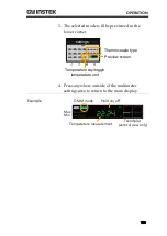
Страница 153: ...Temperature key toggle temperature unit Multimeter settings Preview screen Thermocouple type 4 Press anywhere outside of the multimeter settings area to return to the main display Example Temperature...

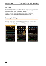
Страница 154: ...in The following apps are available by default Attenuation Calculator Resistance Calculator Calculator Advanced DMM Template Editor and QR Code Link Accessing the EE Apps From the main screen press th...

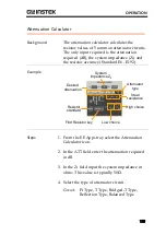
Страница 155: ...192 Example Resistor standard Desired attenuation Attenuator type System impedance Z0 Low choice Ideal resistance High choice Find Resistor key Steps 1 From the EE Apps tray select the Attenuation Cal...

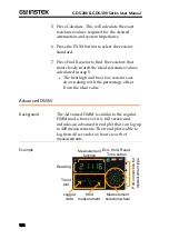
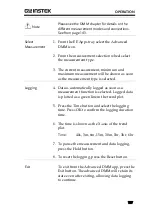
Страница 156: ...tep 5 The best high and best low resistors are shown along with the percentage offset from the ideal value Advanced DMM Background The Advanced DMM is similar to the regular DMM mode however it is ful...

Страница 157: ...ng 4 Data is automatically logged as soon as a measurement function is selected Logged data is plotted as a green line in the trend plot 5 Press the Time button and select the logging time Press OK to...

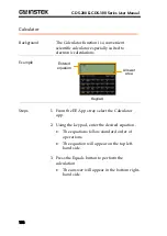
Страница 158: ...lations Example Keypad Entered equation Answer area Steps 1 From the EE Apps tray select the Calculator app 2 Using the keypad enter the desired equation The equations follow standard order of operati...

Страница 159: ...read the QR codes from the QR Code Link app Example QR Code QR Code Options Resistance Calculator Background The resistance calculator can calculate the value of a resistor based on the band code The...

Страница 160: ...and from the pop up window 5 Press Calculate to calculate the value of the resistor Example Color Code Color bands Color code button 4 bands 5 bands Calculate button Resistance value SMD Resistor Valu...

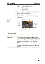
Страница 161: ...resistor Example SMD SMD button 3 digit 4 digit code 2 5 10 Calculate button Resistance value EIA 96 SMD code Template Editor Background The Template Editor function can be used for Go NoGo testing T...

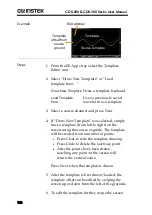
Страница 162: ...4 If Draw New Template was selected simply trace a template from left to right on the screen using the source as guide The template will be created from a number of points Press Clear to redo the tem...

Страница 163: ...n the screen Press OK when done 7 To smooth the template press the Smooth button Points will be removed to smooth the template 8 To save the template press the Save button Choose to save the template...

Страница 164: ...sic configuration for remote control For a command list refer to the programming manual downloadable from the GWInstek website www gwinstek com Interface Configuration 165 Configure USB Interface 165...

Страница 165: ...port needs to be configured to the Communication mode to enable the remote connection Configuration 1 Connect the PC to the GDS 200 300 using the supplied USB A to USB Mini B cable 2 From the Drop Do...

Страница 166: ...the Control panel System Hardware tab Note If you are not familiar with using a terminal application to send receive remote commands please page 167 Using Realterm to Establish a Remote Connection for...

Страница 167: ...alterm can be downloaded on Sourceforge net free of charge For more information please see http realterm sourceforge net Operation 1 Download Realterm and install according to the instructions on the...

Страница 168: ...ht clicking the connected device and selecting the Properties option 4 Start Realterm on the PC as an administrator Click Start menu All Programs RealTerm realterm Tip to run as an administrator you c...

Страница 169: ...ed click on the Port tab Enter the Baud Parity Data bits Stop bits and Port number configuration for the connection The Hardware Flow Control and Software Flow Control options can be left at the defau...

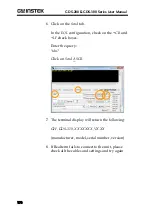
Страница 170: ...check on the CR and LF check boxes Enter the query idn Click on Send ASCII 7 The terminal display will return the following GW GDS 310 XXXXXXX VX XX manufacturer model serial number version 8 If Realt...

Страница 171: ...not appear on the display Make sure you have activated the channel by accessing the vertical menu You can tell if the channel is activated if its channel indicator is to the left of the graticule See...

Страница 172: ...l The Autoset function cannot catch signals under 30mV or 20Hz Please manually set the trigger conditions See page 78 for Autoset details The date and time settings are not correct For date and time s...

Страница 173: ...SMD Resistor Standards 178 EIA 96 Code 178 First Two Digits 178 Multiplier 179 2 5 10 Code 179 Multiplier 179 Last Two Digits 179 GDS 200 300 Default Settings 180 GDS 200 300 Specifications 181 Scope...

Страница 174: ...cifications 183 Basic 183 DC Voltage 183 DC Current 183 AC Voltage 184 AC Current 184 Resistance 184 Diode Test 184 Temperature Thermocouple 184 Continuity Beeper 184 Continuity Beeper 184 GDS 200 300...

Страница 175: ...ill be accessible to the windows file explorer Copy the firmware file to the root directory of the GDS 200 GDS 300 3 From the Utility menu set the USB device port back to the Communication setting 4 F...

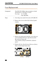
Страница 176: ...500V Steps 1 Turn the power switch off on the GDS 200 300 2 Remove the 4 screws that hold the back panel in place 3 Remove the back panel carefully You will need a case opening tool to pry open the ca...

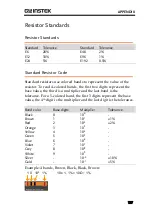
Страница 177: ...present the base value the third is a multiplier and the last band is the tolerance For a 5 colored band the first 3 digits represent the base value the 4th digit is the multiplier and the last digit...

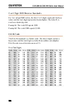
Страница 178: ...Value Code Value Code Value Code Value Code Value 01 100 17 147 33 215 49 316 65 464 81 681 02 102 18 150 34 221 50 324 66 475 82 698 03 105 19 154 35 226 51 332 67 487 83 715 04 107 20 158 36 232 52...

Страница 179: ...ultiplier Letter Code Multiplier F 105 B 101 E 104 A 100 D 103 X or S 10 1 C 102 Y or R 10 2 Last Two Digits 2 Tolerance 5 Tolerance 10 Tolerance Code Value Code Value Code Value Code Value Code Value...

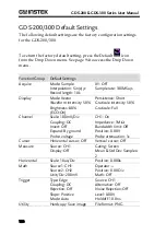
Страница 180: ...intensity 50 Graticule intensity 50 Brightness 80 ECO On Graticule Full Channel Scale 100mV Div CH1 On Coupling DC Impedance 1M Invert Off Bandwidth limit Off Expand By ground Position 0 00V Probe vol...

Страница 181: ...y 3 x Readout 0 1 div 1mV Bandwidth Limit 20MHz 3dB Polarity Normal Invert Offset Position Range 2mV div 50mV div 0 4V 100mV div 500mV div 4V 1V div 5V div 40V 10V div 300V Signal Acquisition Realtime...

Страница 182: ...and Measurement Cursors Voltage difference between cursors V time difference between cursors T frequency measure 1 T Auto measurement 36 sets Auto counter 6 digits Range 2Hz to rated bandwidth Autoset...

Страница 183: ...mm x 136 0mm x 59 7 mm DMM Specifications Basic Reading 50 000 counts 4 digits GDS 307 310 320 3 digits GDS 207 210 220 Voltage Input CAT II 600VRMS CAT III 300VRMS DC Voltage Range 50mV 500mV 5V 50V...

Страница 184: ...e range 10mA Resistance Range 500 5k 50k 500k 5M 5 range Accuracy 500 5k 50k 500k 0 3 3 digits 5M 0 5 5 digits Measure range 50 to 5M Diode Test Maximum forward voltage 1 5V Open voltage 2 8V Temperat...

Страница 185: ...DIX 185 GDS 200 300 Dimensions 10A MAX FUSED V W COM A mA 59 7 136 0 240 2 GDS 220 Digital Storage Oscilloscope 200 MHz 1GSa s M W 16 5pF 300Vrms MAX 1 1 2 CAT 300V CAT II 600V CAT III 300V FUSED 600m...

Страница 186: ...luation regarding the Electromagnetic Compatibility and Low Voltage Directive the following standards were applied EMC EN 61326 1 EN 61326 2 1 EN 61326 2 2 Electrical equipment for measurement control...

Страница 187: ...178 EN61010 measurement category 6 Pollution degree 7 Environment Safety instruction 7 Erase memory 100 Erase Memory 100 FAQ 171 File manager 139 Firmware update 175 Frequency measurements 87 Front pa...

Страница 188: ...ew automatic measurements 89 XY mode 109 Zoom 63 Overshoot measurements 87 Overview Using the touch interface 25 Peak measurements 86 Peak to peak measurement 86 Power on off Safety instruction 7 Prob...

Отзывы: