H-20/35 VR Series Proportioning Unit
12
42942-VR-1, Issue 1
41. HYDRAULIC PRESSURE GAUGE- Indicates the pressure in the Hydraulic Drive
System for the Polyol pump.
42. HYDRAULIC TANK LEVEL GAUGE- Shows the level of oil in the tank.
43. LUBE PUMP SYSTEM (Iso side only)- Continuously circulates Pump Lube to
prevent the crystallization of Isocyanate on the pump shaft.
44. HYDRAULIC DIRECTIONAL VALVE (ISO) - Controls the direction of
hydraulic flow.
45. HYDRAULIC DIRECTIONAL VALVE (POLYOL) - Controls the direction of
hydraulic flow.
46. HOSE HEAT POWER LOCK CONNECTOR- Provides power to the Heated
Hoses.
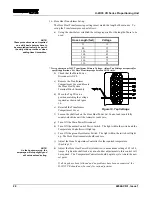
47. TSU HARNESS- Carries the electrical signal from the TSU Sensor in the Iso Hose
to the Hose Heat Temperature Controller.
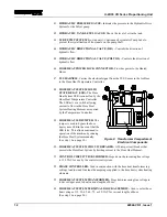
48. HOSE HEAT SYSTEM SOLID
STATE RELAY (SSR)- The Hose
Heat System SSR is controlled by the
Hose Heat Temperature Controller.
The SSR acts as a switch allowing
current to flow in the Hose Heat
System Heating Element as required
by the Temperature Controller.
49. HOSE HEAT SSR JUMPER- The
jumper is used to bypass the hose
heat system SSR in the event that the
SSR fails. This allows continued to
operation of the machine by running
the Hose Heat System manually.
(See step 10 on page 32.)
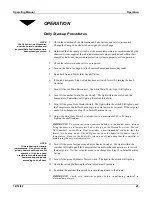
Figure 2. Transformer Compartment
Electrical Components
50. HOSE HEAT SYSTEM CIRCUIT BREAKER- A 50-amp circuit breaker that
protects the Hose Heat System by limiting current to the Hose Heat Element.
51. CONTROL CIRCUIT TRANSFORMER- Steps down the incoming line voltage
to 120 VAC for use by the control circuit system.
52. PHASE CONTROLLER- Used in conjunction with the hose heat transformer tap
settings to adjust and fine tune the amperage supplied to the hose heat system heating
elements.
53. HOSE HEAT SYSTEM TRANSFORMER- Steps down incoming line voltage to
lower voltages used to heat various lengths of hose.
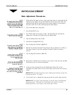
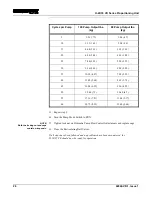
54. HOSE HEAT SYSTEM TERMINAL BLOCK ASSEMBLY- Used to select hose
heat voltage of 15, 30, 45, 60, 75, or 90 VAC for various lengths of hose.
(See step 16 on page 24.)


