GK600 User Manual
Chapter 3 Installation and Wiring
- 45 -
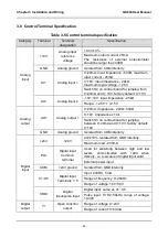
Category
Terminal
Terminal
designation
Specification
Digital
output
Y2/DO
Open collector
out / Pulse out
Open collector output: same as Y1
Pulse output: 0~50kHz;
Relay
output
RA/RB/RC
Control board
relay output
RA-RB: NC; RA-RC: NO
Contact capacity: 250VAC/3A, 30VDC/3A
Terminal
485
Interface
485+
485 differential
Rate:
4800/9600/19200/38400/57600/115200bps
485−
485 differential
signal -
Maximum distance - 500m (standard network
cable used)
GND
485
communication
shield grounding
Isolated from COM interiorly
Control
panel
485
interface
CN4
Control panel
485 interface
Maximum communication distance is 15m
when connected to Control panel
Use standard network cable
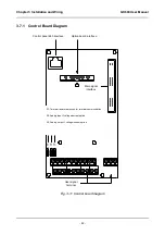
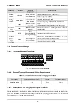
3.9 Control Terminal Usage
3.9.1 Lay-out of Control Terminals
Fig. 3-13 Lay-out of control terminals
3.9.2 Control Terminal Screw and Wiring Requirement
Table 3-6 Terminal screw and wiring specification
Cable type
Cable requirement (mm
2
)
Screw
Torque (kgf.cm)
Shielded cable
1.0
M3
5±0.5
3.9.3 Instructions of Analog Input/Output Terminals
Being particularly vulnerable to noise, analog input & output signal cables should be as short as
possible, shielded, and their shielded layers should be properly grounded close to the side of
drive. The cables should not exceed 20m.

