Chapter 6 Specification of Parameters GK600 User Manual
- 170 -
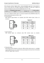
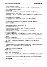
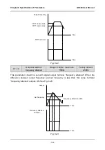
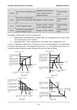
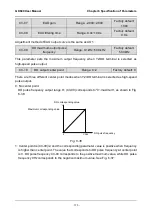
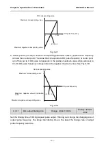
between input pulse signal and frequency setting is defined by curves set by C2-24~C2-27.
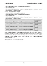
C2-24 and C2-26 represent the range of DI input pulse frequency. C2-25 and C2-27 are the set
values of frequency that corresponds to DI input pulse frequency: 100% corresponds to
positive maximum frequency while -100% corresponds to negative maximum frequency.
ATTENTION:
When pulse input is selected as the frequency setting, X6/DI terminal shall be set to "pulse
input" function (C0-06 is set to 24).
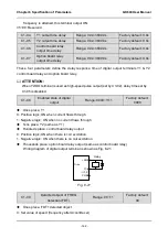
C2-28
DI filtering time
Range: 0.000s~1.000s
Factory default:
0.001s
Defines the filtering time of terminal X6/DI.
C2-29
Target FREQ
Range: 0.00Hz
~
upper limit
frequency
Factory default:
0.0Hz
This parameter should be used together with digital output terminal “Frequency attains
target-frequency set by C2-29” (No.34 in table 6-14). When the error between drive output
frequency and C2-29 value is less than the value of C1-14, terminal “Frequency attains
target-frequency set by C2-29” outputs ON signal.
Group C3 Analog and Pulse Output
C3-00 AO1 output function
Range: 0~99
Factory default: 2
C3-01
EAO output function
(on IO option board)
Range: 0~99
Factory default: 1
C3-02
Y2/DO output function
(when used as DO)
Range: 0~99
Factory default: 0
AO1 and EAO are analog output terminals. When used as high-speed pulse output DO, Y2/DO
terminal's functions are set in C3-02.
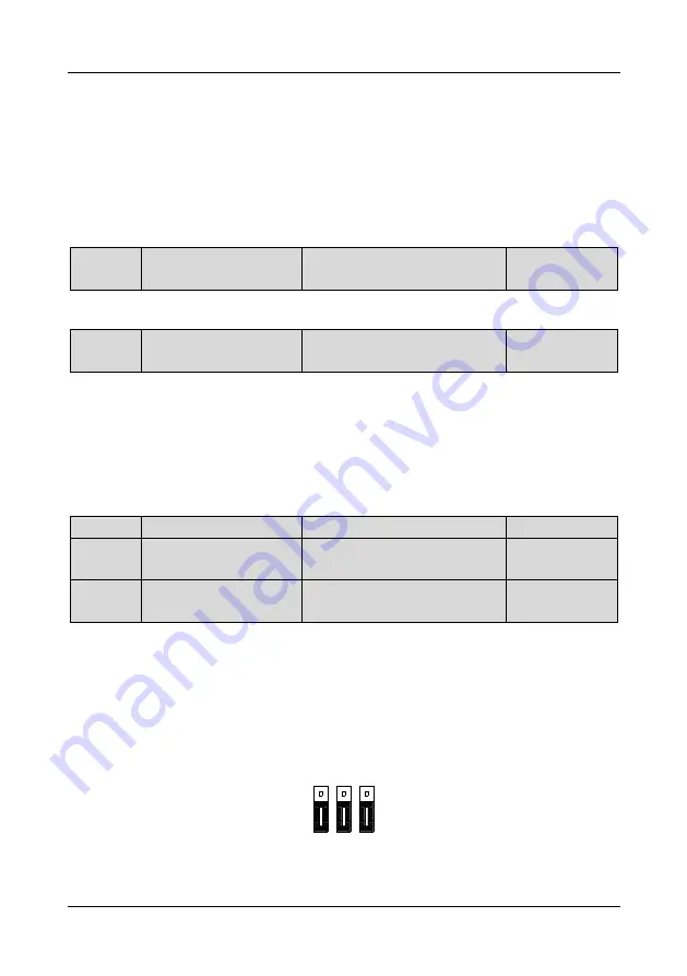
Voltage output or current output of AO1 and EAO can be selected through jumper switch. When
S3 is switched to the position as shown in Fig. 6-33, AO1 output 0~10V. EAO analog output
terminal is located at option board.
Fig. 6-33
OFF
ON
AI1 AO1
485
I
V
V
I
S2
S1
S3

