background image


- 11 - 

HDTV 1000 TD 

a

ssembly

3.1  i

nstalling


the


Casset te

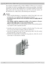
 –  Ensure the head-end station is mounted so it will not be able to vibrate. 

Avoid, for example, mounting the head-end station onto a lift shaft or any 
other wall or floor construction that vibrates in a similar way.


–  Before installing or changing a cassette unplug the power cable from the 

mains power socket. 


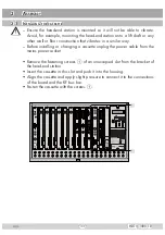
•  Remove the fastening screws 

1

 of an unoccupied slot from the bracket of 

the head-end station. 


•  Insert the cassette in this slot and push it into the housing.


•  Align the cassette and apply slight pressure to connect it to the connections 

of the board and the RF bus bar.


•  Fasten the cassette with the screws 

1

.

1

1

KASSETTE

KASSETTE

KASSETTE

KASSETTE

KASSETTE

KASSETTE

KASSETTE

KASSETTE

KASSETTE

KASSETTE

KASSETTE

KASSETTE

HYBRID-VERSTÄRKER

MESSAUSGANG

–20 dBµV

AUSGANG

max. 106 dBµV

ACHTUNG!

Vor dem Kassettenwechsel

unbedingt 

denNetzstecker ziehen.

CAUTION!

Before 

changing cassettes remove

mains plug.

Grundig SAT S

y

st

e

ms

Содержание HDTV 1000 TD

Страница 1: ...KLASSE HDTV 1000 TD Head End Digital Modulator HDTV COFDM GSS Grundig SAT Systems GmbH Beuthener Strasse 43 D 90471 Nuremberg Phone 49 0 911 703 8877 Fax 49 0 911 703 9210 E mail info gss de Internet http www gss de ...

Страница 2: ...ng 2 ASI ASI MB 8 General 9 2 5 Software query 9 2 6 How the TPS module works 10 Station filter 10 Stuffing 10 Changing the Transport stream and ORGNET ID 10 Changing the NIT 10 Changing the operator ID CAT 10 3 Assembly 11 3 1 Installing the cassette 11 3 2 EMC regulations 12 3 3 Cassette overview 13 3 4 Connecting the cassette 13 3 5 Retrofitting a CA module 14 4 The control panel at a glance 15...

Страница 3: ...ng the DVB mode 27 Input frequency 28 Signal to noise ratio 29 Station filter 30 COFDM parameters 33 Output signal 36 Transmission parameters 37 Transmitter identification 38 Stuffing 38 Setting a substitute signal in the case of an incorrect input signal 39 Transport stream ID and the ORGNET ID 40 Network Information Table NIT 40 Network operator identification 41 Deleting a PID 42 Renaming a PID...

Страница 4: ...cuits No liability is accepted for any damage caused by faulty connections or inappropriate handling Observe the relevant standards regulations and guidelines on the installa tion and operation of antenna systems The standards EN DINEN50083 resp IEC EN DINEN60728 must be observed For further information please read the assembly instructions for the head end station used Test the software versions ...

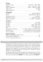
Страница 5: ...lling Seite 51 Unless otherwise noted all values are specified as typical RF input Frequency range 925 2150 MHz Level range 60 dBμV 80 dBμV DVB S modes QPSK 1 2 2 3 3 4 5 6 7 8 DVB S2 modes QPSK 1 2 3 5 2 3 3 4 4 5 5 6 8 9 9 10 8PSK 3 5 2 3 3 4 5 6 8 9 9 10 Symbol rate DVB S QPSK 2 45 MSymb s Symbol rate DVB S2 QPSK 10 30 MSymb s 8PSK 10 31 MSymb s DiSEqC control voltage sound DiSEqC max 65 mA swi...

Страница 6: ...everal channels can be descrambled Remote maintenance Remotely controllable via PSW 1000 yes Remote update via BEflash yes and a corresponding management unit 2 4 Description The double transmodulator cassette is a converter which converts all stations modulated according to DVB S DVB S2 standard into two COFDM modulated signals according to DIN EN 300744 for feeding into a cable network The casse...

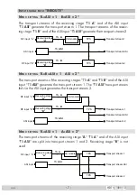
Страница 7: ... 1 ASI 2 The transport streams of the receiving stages TS A and TS B and of the ASI input TS ASI generate the transport stream 1 The TS ASI transport stream fed via the ASI input generates the transport stream 2 Transport stream 1 Transport stream ASI ASI input TPS RF input A RF input B Receiving stage A Receiving stage B CA module Transport stream 2 TS B TS A TS ASI Menu setting A ASI 1 A ASI 2 T...

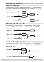
Страница 8: ...eam 1 is made available via the ASI output transport stream 2 via modulator B and the transport stream from the ASI input TS ASI via modulator A MA Modulator B Modulator A Combiner Transport stream 1 Transport stream ASI Transport stream 2 RF output ASI output TS ASI TS 1 TS 2 Menu setting 2 ASI ASI MB Transport stream 1 is made available via modulator A transport stream 2 via the ASI output and t...

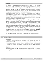
Страница 9: ...output of the cassette to the output collector The common output level of the channel strips can be set at the output collector Additionally a transport stream is made available via the ASI output dependent on the signal path set When the head end station is switched on the two line LC display shows the software version of the control unit To operate this cassette the software ver sion of the cont...

Страница 10: ...te Changing the Transport stream and ORGNET ID The transport stream ID can be changed If the stations of a transponder are split into the transport streams of the channel strips A and B one of the both transport streams a new identification must be allocated to realise the channel search of the settop boxes connected without mistakes If the ORGNET ID is changed a new NIT must be generated Changing...

Страница 11: ...crews 1 of an unoccupied slot from the bracket of the head end station Insert the cassette in this slot and push it into the housing Align the cassette and apply slight pressure to connect it to the connections of the board and the RF bus bar Fasten the cassette with the screws 1 0 1 1 KASSETTE KASSETTE KASSETTE KASSETTE KASSETTE KASSETTE KASSETTE KASSETTE KASSETTE KASSETTE KASSETTE KASSETTE HYBRI...

Страница 12: ... leading in and out for the 19 cabinet are made using cable terminals CLASS KLASSE The attenuation of shielding of the connection lines for ASI and antenna must meet the requirements for Class A Insert the required number of cable terminals in the openings provided in the head end station or in the 19 cabinet Tighten the nuts on the cable terminals until the teeth on the lock washer have penetrate...

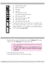
Страница 13: ...ing a PC or notebook and the software BE Flash You can find the current operating software on the website www gss de en 3 4 Connecting the cassette Plug the SAT input cables into the SAT input sockets SAT input A 6 chan nel strip A and SAT input B 8 channel strip B If you need the DiSEqC control the input signal must not be fed via the input distributor The control voltage only serves to control m...

Страница 14: ...table for decoding several channels The hardware and software of this cassette have been thoroughly prepared and tested Any changes made by programme provider to the structures in the pro gramme data might impair or even prevent this function When working with the CA module please read the corresponding operat ing manual from the respective provider Insert the smart card into the CA module so that...

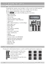
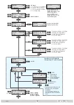
Страница 15: ...evel LNB oscillator frequency control voltage Input symbol rate Input frequency Station filter CA module if available Output signal Transmission parameters Station identification Stuffing Substitute signal Transport stream and ORGNET ID Network Information Table NIT Network operator identification Deleting a PID Renaming a PID Factory reset 4 2 Control panel The key pad on the head end station is ...

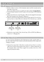
Страница 16: ... chan nel strip there is a status LED which indicates if the channel strip is switched on Status LED Channel strip B Status LED Channel strip A Balance the output levels of the channel strips A and B if the difference in level is 1 dB page 25 5 2 Notes on level setting In order to prevent interference within the head end station and the cable sys tem the output level of the cassette must be decrea...

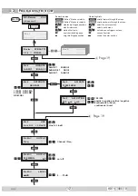
Страница 17: ... burst continuous burst Bx 4 188 pos cont ASI OPTION Ein On Box 1 Bx 1A C5 12 S3 24 TWIN SAT C07 Böx 4 C5 12 S3 24 TWIN SAT C07 Box 5 Bx 4A B 10600 MHz LNB off off abcd a T Ton sound D DiSEqC b A B 0 15 0 F hex c H V horizontal vertical Bedienhinweise blättert Menüs vorwärts blättert Menüs rückwärts wählen die Eingabeposition wählt Untermenü stellen Werte ein speichert alle Eingaben 1 zeigt die Ei...

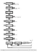
Страница 18: ...QAM64 COFDM MODE POS 5 8MHz QPSK QAM64 positiv negativ positive negative Bx 4A B 2k C7 8 COFDM MODE G1 32 2 8k C1 2 C7 8 G1 4 G 1 32 M M M Kanalzug A mit CA Modul Channel strip A with CA module Bx 4A Menu CA Edit Die angezeigte Information ist abhängig vom verwendeten CA Modul The information displayed is dependent on the CA module used Bx 4A 01 03 Information MENU Bx 4A TV X 04 09 X entschlüsseln...

Страница 19: ... 4A B Single Carrier FAILURE Null Packets Single Carrier Bx 4A B off NIT Make on off Make Bx 4A B PID 0x0000 DROP off Bx 4A B 0xDE00 CAT ID off Bx 4A B 0x0000 0000 REMAP off on off on off on off Bx 4A B 0x0001 0100 TS ONID off off on used M M B A A Bx 4 Defaults FACTORY Bx 4 STORE FACTORY M speichern store auf Werkseinstellung zurücksetzen und speichern reset to factory defaults and store Page 17 ...

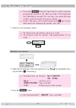
Страница 20: ...tte menu item Switch on the head end station The display shows the software version e g V 44 The processor reads the cassettes data approximately 10 sec onds Ein On BE Remote please wait V 44 t 10 s Selecting the cassette Box 1 Box 5 Box 4 V 34 DVBS2 TPI COFDM Select the cassette you want to programme e g Box 4 by repeatedly press ing the button if necessary The display shows e g the menu Box 4 DV...

Страница 21: ... The Output signal path OUTROUTE menu is activated Output signal path In this menu you define the signal path of the output transport streams Menu setting ASI ASI page 8 Menu setting 1 ASI ASI MA page 8 Menu setting 2 ASI ASI MB page 8 Bx 4 ASI ASI OUTROUTE Use the buttons to select the signal path wished If you do not want to do ASI settings press the button The Selectingthechannelstrip LINE menu...

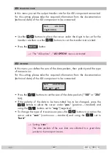
Страница 22: ...size of the data packets their polarity and the type of transmission For this setting please take the required information from the documentation technical data of the ASI component to be connected Bx 4 188 pos cont ASI OPTION Press the buttons to set the size of the data packets 188 or 204 bits If the polarity of the data to be transmitted has to be changed press the buttons to place the cursor u...

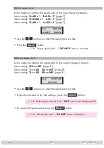
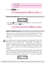
Страница 23: ... setting covers the range from 42 0 MHz to 860 0 MHz The COFDM signal is normally transmitted with a bandwidth of 8 MHz This means that you can only use the channel centre frequency of the existing chan nel grid in the range of channels C21 C69 frequency grid 8 MHz The CCIR channel grid is 7 MHz in the range of the lower frequency bands chan nels C5 C12 If 8 MHz COFDM signal packages are transmitt...

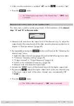
Страница 24: ...e output frequency of the channel strip 42 0 860 0 MHz Additionally the modulator of the channel strip can be switched off or on page24 Bx 4A B 850 00MHz OUTPUT on Use the buttons to place the cursor under the digit to be set for the frequency display then use to set the output frequency wished Switching the modulator off or on Bx 4A B C21 OUTPUT on To switch off the modulator place the cursor und...

Страница 25: ...other cassettes please pay attention to chapter 6 Final procedures page 49 By repeatedly pressing the button scroll back to the Selecting the channel strip menu Select the other channel strip page 23 and set the following menu items Channel frequency setting page 23 Output channel or Output frequency page 24 Switch on the modulator if necessary page 24 Measure and note down the output level Activa...

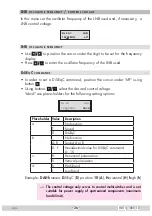
Страница 26: ...position the cursor under off using button Using buttons select the desired control voltage abcd are place holders for the following setting options Bx 4A 10600 MHz LNB abcd Place holder Value Description a _ No function T Sound D DiSEqC b _ No function A B Sound A or B 0 F Hexadecimal value for DiSEqC command 0 15 c H Horizontal polarisation V Vertical polarisation d h High Band l Low Band Exampl...

Страница 27: ...nders can be found in the current chan nel table of the satellite operator in various satellite magazines and in the Internet Bx 4A B 27500 SYMBOL DVB S Use to position the cursor under the digit to be set for the symbol rate displayed Press to enter the respective digit of the symbol rate needed Repeat the procedure by the quantity of the digits to be set Setting the DVB mode The cassette recogni...

Страница 28: ...tion mark appears in the second line of the display there is no input signal present In this case check the configuration of the antenna system and head end station as well as the preceding settings of the cassette Bx 4A B 11836 1 8 FREQ CN 12 Bx 4A B 12 0 dB C N 9 6 OK Use to position the cursor under the digit of the frequency displayed to be set Press to set the respective digit of the input fr...

Страница 29: ...indicates the quality of the received transport stream 1 2 3 4 5 6 7 8 9 7 Status LED channel strip A 9 Status LED channel strip B LED indicator Indication Green Signal quality is good Yellow Signal quality is insufficient Red No signal Off The channel strip modulator is switched off Press the button to return to the main menu If the input signal path A B ASI 1 ASI 2 is selected the station filter...

Страница 30: ... sta tions are inactive and can be added to the transport stream selectively The figure of the menu below is dependent on the setting of the Input signal path menu page 21 The menu shows the setting A B ASI 1 ASI 2 With this setting the transport stream of channel strip B is routed to the trans port stream of channel strip A and therefore cannot be set in channel strip B Programming channel strip ...

Страница 31: ...ows e g Bx 4A TV 01 10 Das Erste Meaning of the indicators in the example Bx 4A Slot 4 channel strip A TV TV channel type The currently selected station is switched on 01 10 The 1st of 10 stations is being displayed Das Erste Station name Further possible terms displayed RA Radio channel type For radio stations the background of the screen of the connected TV or test receiver is darkened The curre...

Страница 32: ...g PIDs audio video text are inserted into the data stream and the PAT and SDT tables are updated Test the status of the individual stations If the filter is switched on press the button In this mode you can test the set tings of the station filters again or change them if necessary In the PROGRAM Filter on menu the station filters switched on can be switched off using the buttons if necessary Menu...

Страница 33: ...on of the net data rate into the gross data rate displayed in the Stuffing menu page 38 is made according to the following formula 204 x net data rate Gross data rate 188 Net data rate kbit s at a bandwidth of 8 MHz Guard interval Modulation Code rate 1 4 1 8 1 16 1 32 QPSK 1 2 4976 5529 5855 6032 2 3 6635 7373 7806 8043 3 4 7465 8294 8782 9048 5 6 8294 9216 9758 10053 7 8 8709 9676 10246 10556 16...

Страница 34: ...17930 18473 64 QAM 1 2 13063 14515 15369 15834 2 3 17418 19353 20491 21112 3 4 19595 21772 23053 23751 5 6 21772 24191 25614 26390 7 8 22861 25401 26895 27710 Net data rate kbit s at a bandwidth of 6 MHz Guard interval Modulation Code rate 1 4 1 8 1 16 1 32 QPSK 1 2 3732 4147 4391 4524 2 3 4976 5529 5855 6032 3 4 5599 6221 6587 6786 5 6 6221 6912 7318 7540 7 8 6532 7257 7684 7917 16 QAM 1 2 7465 8...

Страница 35: ...ce f kHz 4 4643 2 232 1 116 n carrier theoretical 2048 4096 8192 n carrier real 1705 3410 6817 Used bandwidth MHz 6 66 6 66 6 66 Total symbol duration TGS µs 320 288 272 264 620 576 544 528 1280 1152 1088 1056 Guard interval TG µs 64 32 16 8 128 64 32 16 256 128 64 32 TG TS 1 4 1 8 1 16 1 32 1 4 1 8 1 16 1 32 1 4 1 8 1 16 1 32 Transmission parameters for DVB T at a bandwidth of 6 MHz Transmission ...

Страница 36: ...ODE POS Use to set the bandwidth of the output signal 5 MHz 8 MHz Carrier modulation In this menu item the carrier modulation is set At this the setting QPSK corre sponds to the lowest and the setting QAM64 to the highest output data rate Use the buttons to place the cursor under QPSK QAM Set the carrier modulation of the output signal using the buttons QPSK QAM16 QAM64 Spectral position inverting...

Страница 37: ...is data redun dancy is added to the signal to be transmitted forward error correction The factor of the quantity of redundancy contained in the bits transmitted is called code rate Using the setting C7 8 you can get the highest output data rate at lowest re dundancy Use the buttons to place the cursor under C Set the code rate required using the buttons C1 2 C2 3 C3 4 C5 6 C7 8 Guard interval In t...

Страница 38: ... digit of the hexadeci mal number to be set Press to set the respective digit of the hexadecimal number Repeat the procedure by the quantity of the digits to be set Using the button place the cursor under off and switch on the trans mitter identification using the buttons By pressing the button you return to the hexadecimal number setting Press the button The Stuffing STUFFING menu is activated St...

Страница 39: ...ber 1 question marks ap pear in the display In this case correct the COFDM settings pages 36 or the settings of the station filter page 30 Bx 4A 34363 36906 STUFFING Press the button The Setting a substitute signal in the case of an incorrect input signal FAILURE menu is activated Setting a substitute signal in the case of an incorrect input signal You use this menu to set whether a COFDM signal f...

Страница 40: ...ci mal number to be set Press to set the respective digit of the hexadecimal number Repeat the procedure by the quantity of the digits to be set Using the button place the cursor under off and switch on the trans mitter identification using the buttons By pressing the button you return to the hexadecimal number setting Press the button The Network Information Table NIT menu is activated Network In...

Страница 41: ...on by pressing the button the previously generated NIT is added again If you have changed parameters in the meantime you must first select Make to generate a new up to date NIT Press the button The Network operator identification CAT ID menu is activated Network operator identification In this menu you can change the network operator identification CAT ID Conditional Access Table Identification fo...

Страница 42: ...ot modified appears in the display Press the button The Deleting a PID DROP menu is activated Deleting a PID In this menu a PID of the transport stream can be deleted Bx 4A B PID 0x0000 DROP off Use the buttons to place the cursor under the respective digit of the hexadecimal number of the PID to be deleted 0x0000 and set the hexa decimal number using Use the button to set the cursor under off and...

Страница 43: ...spective digit of the hexadecimal number of the PID to be changed 0x0000 and set the hexadecimal number using Use the buttons to place the cursor under the respective digit of the hexadecimal number of the new PID 0000 Set the hexadecimal number using Use the button to set the cursor to off and rename the PID using the buttons on Press the button The Factory reset FACTORY Defaults menu is activate...

Страница 44: ...ts are saved The display shows STORE Back to Selecting the cassette page 20 By pressing the button you will be returned to the menu item Selecting the channel strip without saving the factory defaults page 23 If necessary set channel strip B Saving settings Press the button Returning to Selecting the cassette menu page 20 The settings are saved If functions of the TPS module are activated their st...

Страница 45: ...crambled broadcasts within one service e g scrambled stations and un scrambled regional broadcasters The PID monitoring CA menu is activated PID monitoring The factory default of the PID monitoring is switched on If particular PIDs are not decrypted the CI module is reset Additionally drop outs may occur if several stations are decrypted To prevent this the PID moni toring can be switched off Bx 4...

Страница 46: ...iguring the CA module CA menu and activate the Output signal COFDM MODE menu page 36 Press the button to activate the menu of the CA module Bx 4A 01 03 Information MENU The display shows e g Bx 4A 01 03 MENU Information Meaning of the indicators Bx 4A Slot 4 channel strip A 01 03 The first of three menu items is activated MENU The menu of the CA module is activated For the explanation of further d...

Страница 47: ... to be descrambled Bx 4A Menu CA Edit Bx 4A 01 03 Information MENU Bx 4A TV X 04 09 Å Ï M Bx 4A 01 03 Information MENU Ï M The display shows e g Bx 4A TV X 04 09 Meaning of the indicators in the example Bx 4A Slot 4 channel strip A TV TV channel type X The currently selected station is to descramble 04 09 The 4th of 9 stations read is being displayed Station name Further possible terms displayed R...

Страница 48: ...anges and activate the station filter Press the button The filter is activated The display shows the Configuring the CA module CA menu Bx 4A Menu CA Edit Press the button The Output signal COFDM MODE menu is activated page 36 ...

Страница 49: ...th current EMC regulations securely Securely tighten the cable connections using an appropriate open ended spanner Measure the output levels of the other cassettes and tune them to a uniform output level using the appropriate level controls or software dependent on the head end station used Please regard the assembly instructions of the respective head end station Mount the front cover see assembl...

Страница 50: ...26 514 00 C 27 522 00 C 28 530 00 C 29 538 00 C 30 546 00 C 31 554 00 C 32 562 00 C 33 570 00 C 34 578 00 C 35 586 00 C 36 594 00 C 37 602 00 C 38 610 00 C 39 618 00 C 40 626 00 C 41 634 00 C 42 642 00 C 43 650 00 C 44 658 00 C 45 666 00 C 46 674 00 C 47 682 00 C 48 690 00 C 49 698 00 C 50 706 00 C 51 714 00 C 52 722 00 C 53 730 00 C 54 738 00 C 55 746 00 C 56 754 00 C 57 762 00 C 58 770 00 C 59 7...

Страница 51: ... 51 HDTV 1000 TD Declaration of CE conformity ...

Страница 52: ...Alterations reserved Technical data E O E GSS GmbH V34 17072013 Service Phone 49 0 911 703 2221 Fax 49 0 911 703 2326 Email service gss de ...

Отзывы: