- 10 -
HDTV 1000 S
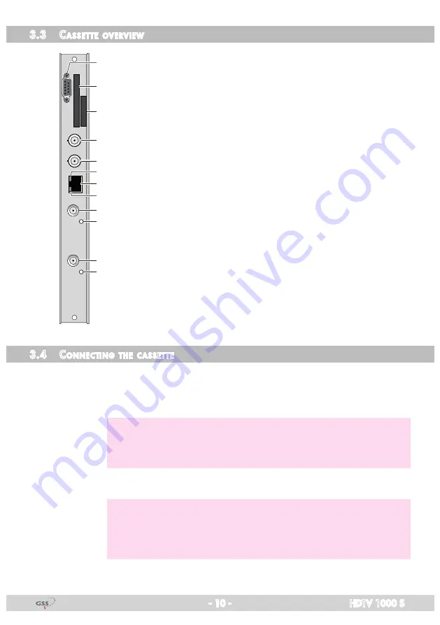
3.3 C
asset te
overview
5
6
7
8
9
!
@
2
1
4
3
0
1
Status LED of channel strip "
B
"
2
SAT IF input of channel strip "
B
"
3
Status LED of channel strip "
A
"
4
SAT IF input of channel strip "
A
"
5
Status LED of the LAN interface (data transfer)
6
LAN socket
7
Status LED of the LAN interface (network connection)
8
not used
9
not used
0
Type label
!
Slot for a CA module
@
D-SUB socket "RS 232"
The operating software of the cassette can be updated via the
9-pin D-SUB socket "RS 232" using a PC or notebook and the
software "
BE-Flash
".
You can find the current operating software on the website
"
www.gss.de/en
".
3.4 C
onneCting
the
Casset te
• Connect the RF connections to the inputs
4
(channel strip "
Tuner A
") and
2
(channel strip "
Tuner B
"). To connect a DiSEqC controlled multi switch 2
F jack-to-jack adapters (cable connectors) are attached.
—> The control voltage for a DiSEqC controlled multi switch which is
present at the antenna input is not suitable as its power supply.
Use an external power supply.
• Connect the LAN socket
6
.
—> In order to avoid restrictions of the network data rate (and therefore
possible disturbances) we recommend to operate other applications
like e.g. Internet, VOIP telephony etc. in separated networks.
—>
Exclusively use "Layer 3 switches", which support the IGMP protocol.


