- 27 -
HDMT 1000 ASI LAN / HDMT 1001 C
ÀiViÛiÀÃÊV>ÊÀiViÛiÊLÌ Ê`>Ì>ÊÃÌÀi>ÃÆÊÊ«ÀiÀÊÀiVi«ÌÊV`ÌÃ]ÊÞÊ
the “HP” portion.
Bx 4A
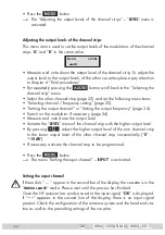
Priority:
high
INPUT
UÊ ÞÊ«ÀiÃÃ}Ê
set to “
high
“ or “
low
“
(not relevant in the case of standard modulation).
Ê
UÊ *ÀiÃÃÊÌ iÊ
button.
—> The menu “Setting the station filter ” – “
PROGRAM
” is activated.
Setting the station filter
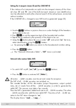
If no station is found the error message “
FILTER no Service
” is displayed.
Check the configuration of the antenna system and head-end station as well as
the previous settings of the cassette in question.
If the input signal path “
A+B+ASI=1 ASI=2
” is selected the station filter of
channel strip “
B
” is used in the channel strip “
A
”. Therefore perform the setting
for channel strip “
B
»Ê«ÕÌÊV >i®Ê>VVÀ`}ÊÌÊ«>}iÊÓÎ]ÊLivÀiÊ>VÌÛ>Ì}Ê
the “Setting the station filter” – “
PROGRAM
” menu.
If the input signal path “
A+ASI=1 B+ASI=2
” or “
A+ASI=1 A+ASI=2
” is se-
lected the channel strips can be programmed one after the other.
The default setting for the station filter is “
off
”. In this menu you define the sta-
tions received to be transmitted. If stations are activated the output data rate
increases.
If the station filter is switched off (factory default) all stations of the transport
stream passes the station filter. As soon as the station filter is activated all sta-
tions are inactive.
The figure of the menu below is dependent on the setting of the “Selecting the
input signal path” menu (page 21).
The menu shows the setting ”
A+B+ASI = 1 ASI = 2
”.
With this setting the transport stream of channel strip “
B
” is routed to the trans-
port stream of channel strip “
A
” and therefore cannot be set in channel strip
“
B
”. Programming channel strip “
B
” the transport stream coming from the ASI
input can be processed only.


