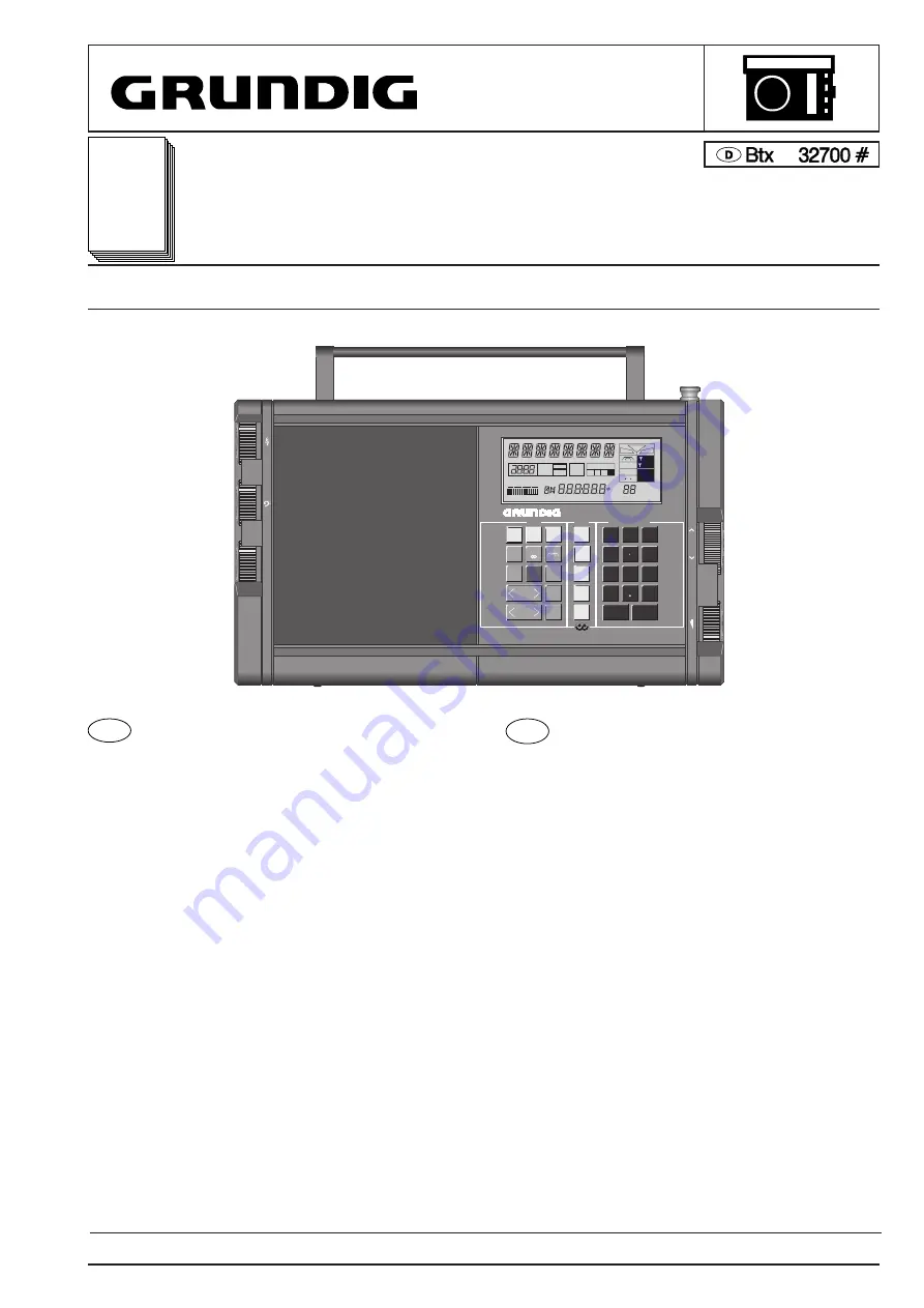
Grundig Satellit 700 Скачать руководство пользователя страница 1

Service 

Manual

Satellit 700

Satellit 700 (9.15055-8151) / Satellit 700 USA (9.15055-7151) / Satellit 700 GB (9.15055-6251) / Satellit 700 Italia (9.15055-6151)

Änderungen vorbehalten

Printed in Germany

Service Manual Sach-Nr. 72010-719.55

Subject to alteration

VK 225  1291

Service Manual Part No.

72010-719.55

*

SERVICE MANUAL

AGC            MGC

LC  DATA  MONITOR

MODE

CALL

DIRECT-KEY-INPUT

RADIO-DATA-SYSTEM

R•D•S

WORLD RECEIVER

EXCHANGEABLE MEMORY FILES  COPY FUNCTION

700

+

-

+

-

+

-

VOLUME

TUNING

TIME II

AUTO

ROM

TABLE

MEMOFILE

1   2   3   

4

MONO

ACCU

MGC

EXT

LOC

LSB

USB

SYNCH

MHz

R D S

kHz

MEMORY

m

0   1   2   3   4   5

TUNING

BATT./ACCU

1

2

3

4

5

6

7

8

9

0

AM

AUTO

FREE

TIME

I/II

USB

LSB

MENU

A-Z
0-9

MEMORY

FILE

MEMORY

SCAN

SEARCH

SELECT

SATELLIT

STEREO

SLEEP

FREQUENCY

m-BAND

MEMO

AF

ON/OFF

FM/

RDS-AF

MONO

STORE

SYNCH

SLEEP

CL

Inhaltsverzeichnis

Seite

Technische Daten ........................................................................... 2
Allgemeine Hinweise:

Sicherheitshinweise ............................................................... 3-5
Sicherheitshinweise zu Lithiumbatterien .................................. 5
Chip-Technik ......................................................................... 6-7
Behandlung von MOS-Bauteilen ........................................... 7-8

Ausbauhinweise ......................................................................... 9-10
Hinweise zum Satellit 700:

Spannungsversorgung ........................................................... 11
Autom. Steuerung eines Cassettengerätes ............................ 12
Befestigen des Gerätes .......................................................... 12
Memofiles ............................................................................... 12
Lautsprecher-Buchse ............................................................. 12
Synchrondetektor ................................................................... 13
RDS-Testmode ....................................................................... 13

Testmode ...................................................................................... 14
Abgleich ................................................................................... 15-18
Schaltbilder:

HF-Platte ........................................................................... 23-26
Prozessorplatte .................................................................. 27-30
Bedienplatte ....................................................................... 35-37
NF- und Potiplatte .............................................................. 38-40

Druckplattenabbildungen:

HF-Platte ........................................................................... 19-22
Prozessorplatte .................................................................. 31-32
Bedienplatte ....................................................................... 33-34
NF- und Potiplatte .............................................................. 41-42

Schaltbildhinweise ........................................................................ 43
Ersatzteilliste ............................................................................ 44-52

Contents

Page

Specification .................................................................................... 2
General Notes:

Safety Requirements ............................................................. 3-5
Safety Cautions for Lithium Batteries ....................................... 5
Chip Technology .................................................................... 6-7
Handling of MOS Chip Components ..................................... 7-8

Disassembly Instructions ........................................................... 9-10
Notes for the Satellit 700:

Power Supply ......................................................................... 11
Autom. Control of a Cassette Recorder .................................. 12
Securing the Unit .................................................................... 12
Memofiles ............................................................................... 12
Loudspeaker Socket ............................................................... 12
Synchronous Demodulator ..................................................... 13
RDS-Testmode ....................................................................... 13

Testmode ...................................................................................... 14
Alignment ................................................................................. 15-18
Circuit Diagrams:

RF Board ........................................................................... 23-26
Processor Board ................................................................ 27-30
Operating Board ................................................................ 35-37
AF- and Potentiometer Board ............................................ 38-40

Illustration of Printed Boards:

RF Board ........................................................................... 19-22
Processor Board ................................................................ 31-32
Operating Board ................................................................ 33-34
AF- and Potentiometer Board ............................................ 41-42

Notes for the Circuit Diagram ........................................................ 43
List of Spare Parts ................................................................... 44-52

D

GB

Содержание Satellit 700

Страница 1: ...ise 9 10 Hinweise zum Satellit 700 Spannungsversorgung 11 Autom Steuerung eines Cassettenger tes 12 Befestigen des Ger tes 12 Memofiles 12 Lautsprecher Buchse 12 Synchrondetektor 13 RDS Testmode 13 Te...

Страница 2: ...MHz IF 2 450 kHz Technische Daten Spannungsversorgung Durch Batterien 4 x 1 5 V Monozellen IEC LR20 oder 4 x handel bliche 4 Ah Akkus in gleicher Gr e IEC KR 35 62 Eingebaute sich automatisch wiedera...

Страница 3: ...der besch digt noch offensichtlich ungeeignet sein Dies gilt besonders f r Isolierungen und Isolierteile Netzleitungen und Anschlu leitungen sind auf u ere M ngel vor dem Anschlu zu pr fen Isolation p...

Страница 4: ...i deve comunicare per iscritto all utilizzat la pericolosit dell apparecchio riguardo il suo isolamento Raccomandazione per il servizio assistenza M M Impiegare solo componenti originali I componenti...

Страница 5: ...rounded so as to provide some protection against voltage surges and built up static charges Section 810 of the National Electrical Code ANSI NFPA No 70 1984 provides informa tion with respect to prope...

Страница 6: ...components Use only low voltage soldering irons with temperature control Permissible soldering temperatures are approx 240 C up to max 300 C Keep the soldering period as short as possible Keep the CHI...

Страница 7: ...S components in conductive packages until they are used MOS components must never be stored or transported in Styropor materials or plastic magazines 2 Persons have to rid themselves of electrostatic...

Страница 8: ...s que trabajan con elementos MOS deben descargarse previamente tocando un objecto puesto a tierra 3 Los elementos MOS s lo deben cogerse por la c psula sin rozar siquiera los terminales 4 Pruebas y tr...

Страница 9: ...A A A A I C C E E F F D B BU5 B I Ausbauhinweise Disassembly Instructions Satellit 700 GRUNDIG Service Technik Ausbauhinweise Disassembly Instructions 9...

Страница 10: ...bauen und ffnen Displaylampen ausl ten Rear Panel Unscrew 4 screws A Lift the rear panel at the bottom side and remove it carefully Disconnect the battery plus wire RF Board Unscrew 5 screws B Disconn...

Страница 11: ...n Sie bitte die Sicherheitshinweise f r Lithiumbatterien auf Seite 5 ACCU GB Notes for the Satellit 700 Power Supply Battery or Accumulator Operation With 4 HP2 batteries IEC LR 20 alkaline manganese...

Страница 12: ...cassette recorder operates potential free The switching voltage delivered by the cassette recorder max 30V 500mA ischanged by the switch jack as follows Securing the Unit The Satellit 700 can be secu...

Страница 13: ...ing _ _ in any test function means that no RDS signals can be decoded The Test Mode is terminated by pressing the button for more than 3s or by switching the receiver off Synchrondetektor Reicht die B...

Страница 14: ...laytrei bers 2 Taste A Z Anzeige aller Segmente COMMON 2 des Displaytrei bers 2 Taste MENU Anzeige aller Segmente Button AUTO All segments of COMMON 1 of the display driver 1 lights up Button SLEEP Al...

Страница 15: ...len F7 10B mitSendersignal1612kHz 400Hz 30 abschlie end auf NF Maximum an Me punkt 17 oder 18 abgleichen Alignment At batterie voltage UB 6 V Operating Unit Clock frequency Presettings none Feeding no...

Страница 16: ...mV f 22 5 kHz Messung Klirrfaktormessger t an Me punkt 15 Abgleich Mit L 504 15 bei 95 MHz Minimum einstellen SW RF circuit Presettings SW Aerial switch to INT Distant Local switch to DX unsolder the...

Страница 17: ...gleich Mit R 605 17 Minimum einstellen Einspeisung Stereosender an Antennenbuchse FM 95 MHz 1 mV linker Kanal moduliert Messung NF Voltmeter ber Tiefpa an Me punkt 18 Abgleich Mit R 605 17 gegebenenfa...

Страница 18: ...223 61 CC 0147 223 55 CC 0148 220 59 CC 0149 216 59 CC 0150 198 72 CC 0151 218 59 CC 0152 219 73 CC 0153 221 68 CC 0155 224 78 CC 0156 214 58 CC 0201 37 65 CC 0202 42 63 CC 0203 43 69 CC 0204 38 76 C...

Страница 19: ...echnik X 20 30 40 50 60 70 80 90 100 110 120 130 140 150 160 170 180 190 200 210 220 230 Y 150 130 120 160 140 110 100 70 60 50 40 30 80 90 6 1 6 1 7 12 6 1 7 12 4 6 3 1 4 6 3 1 4 6 3 1 4 6 3 1 1 3 6...

Страница 20: ...24 23 Schaltbild HF Platte Circuit Diagram of RF Board Satellit 700 GRUNDIG Service Technik Schaltbild HF Platte Circuit Diagram of RF Board Satellit 700 GRUNDIG Service Technik...

Страница 21: ...25 26 Satellit 700 Schaltbild HF Platte Circuit Diagram of RF Board GRUNDIG Service Technik Satellit 700 Schaltbild HF Platte Circuit Diagram of RF Board GRUNDIG Service Technik...

Страница 22: ...27 Schaltbild Prozessorplatte Circuit Diagram of Processor Board Satellit 700 GRUNDIG Service Technik Schaltbild Prozessorplatte Circuit Diagram of Processor Board Satellit 700 GRUNDIG Service Techni...

Страница 23: ...30 Satellit 700 Schaltbild Prozessorplatte Circuit Diagram of Processor Board GRUNDIG Service Technik Satellit 700 Schaltbild Prozessorplatte Circuit Diagram of Processor Board GRUNDIG Service Techni...

Страница 24: ...104 76 CR 1162 19 76 CR 1163 19 78 CR 1164 19 81 CR 1165 19 83 CR 1166 67 48 CR 1167 58 80 CR 1168 43 81 CR 1169 58 75 CR 1171 58 78 CR 1172 58 73 CR 1173 52 58 CR 1174 54 61 CR 1175 51 63 CR 1176 10...

Страница 25: ...24 155 159 CR 0025 151 153 CR 0026 152 143 CR 0027 153 140 CR 0028 154 138 CR 0029 155 135 CR 0031 231 135 CR 0032 226 138 CR 0033 226 135 CR 0035 168 64 CR 0037 141 131 CR 0041 166 74 CR 0045 143 66...

Страница 26: ...36 35 Schaltbild Bedienplatte Circuit Diagram of Operating Board Satellit 700 GRUNDIG Service Technik Schaltbild Bedienplatte Circuit Diagram of Operating Board Satellit 700 GRUNDIG Service Technik...

Страница 27: ...Satellit 700 Schaltbild Bedienplatte Circuit Diagram of Operating Board GRUNDIG Service Technik 37...

Страница 28: ...Satellit 700 Schaltbild NF und Potiplatte Circuit Diagram of AF and Potentiometer Board GRUNDIG Service Technik 38...

Страница 29: ...haltbild NF und Potiplatte Circuit Diagram of AF and Potentiometer Board GRUNDIG Service Technik 39 Satellit 700 Schaltbild NF und Potiplatte Circuit Diagram of AF and Potentiometer Board GRUNDIG Serv...

Страница 30: ...R 0737 88 181 CR 0738 82 172 CR 0742 42 46 CR 0743 39 46 CR 0744 38 35 CR 0745 36 31 CR 0746 38 31 CR 0747 46 31 CR 0749 43 31 CR 0752 78 21 CR 0753 78 24 CR 0754 126 22 CR 0755 126 30 CR 0761 76 97 C...

Страница 31: ...Satellit 700 GRUNDIG Service Technik Schaltbildhinweise Notes for the Circuit Diagram 43...

Страница 32: ...303 136 01 KOAXSTECKER COAXIAL PLUG 0056 000 09623 436 00 BUCHSE SOCKET 0057 000 09623 410 00 CINCHBUCHSE CHINCH SOCKET 0058 000 09623 383 00 FREMDSPANNUNGSBUCHSE EXTERNAL VOLTAGE SOCKET 0059 000 0962...

Страница 33: ...FQ 0805 0 01 UF 10 CC 436 8672 160 139 KEFQ 0805 270PF 5 CC 437 8672 267 187 KEFQ 1206 0 1 UF 10 CC 438 8672 267 179 KEFQ 1206 0 047UF 10 NDERUNGEN VORBEHALTEN ALTERNATIONS RESERVED C 127 8699 999 335...

Страница 34: ...3 KEFQ 0805 0 01 UF 10 CC 811 8672 160 146 KEFQ 0805 1000PF 5 CC 813 8672 198 173 KEFQ 0805 0 01 UF 10 CC 814 8672 198 173 KEFQ 0805 0 01 UF 10 CC 817 8672 198 173 KEFQ 0805 0 01 UF 10 CC 821 8672 160...

Страница 35: ...209 8706 100 089 R CHIP 0805 4 7 KOHM 5 CR 211 8706 100 057 R CHIP 0805 220 OHM 5 CR 212 8706 100 113 R CHIP 0805 47 KOHM 5 CR 213 8706 100 121 R CHIP 0805 100 KOHM 5 CR 214 8706 100 097 R CHIP 0805...

Страница 36: ...05 3 3 KOHM 5 CR 538 8706 100 081 R CHIP 0805 2 2 KOHM 5 CR 602 8706 100 097 R CHIP 0805 10 KOHM 5 CR 604 8706 100 073 R CHIP 0805 1 KOHM 5 CR 606 8706 100 089 R CHIP 0805 4 7 KOHM 5 CR 607 8706 100 1...

Страница 37: ...0805 68 KOHM 5 CR 908 8706 100 121 R CHIP 0805 100 KOHM 5 CR 909 8706 100 097 R CHIP 0805 10 KOHM 5 CR 911 8706 100 097 R CHIP 0805 10 KOHM 5 CR 912 8706 100 097 R CHIP 0805 10 KOHM 5 CR 914 8706 100...

Страница 38: ...0 SMD TRANS BF 840 CT 304 8301 130 543 SMD TRANS BF 543 E 7810 CT 305 8301 130 550 SMD TRANS BF 550 CT 306 8301 130 543 SMD TRANS BF 543 E 7810 CT 401 8301 130 550 SMD TRANS BF 550 CT 402 8301 130 543...

Страница 39: ...R NDERUNGEN VORBEHALTEN ALTERNATIONS RESERVED D 11 8309 215 043 DIODE 1 N 4151 PHI TFK D 12 8309 215 043 DIODE 1 N 4151 PHI TFK D 13 8309 215 043 DIODE 1 N 4151 PHI TFK D 14 8309 215 043 DIODE 1 N 415...

Страница 40: ...SB EXCHANCEABLEMEMORYFILESCOPYFUNCTION SATELLIT 700 1 15055 095 01 44 09622 819 01 14 15054 099 01 SATELLIT 700 12 15054 098 01 3 15055 035 00 12 15054 098 01 LA 1 8316 113 109 LAMPE T1 5V 60MA 683 1...

Отзывы: