background image

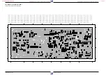
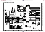
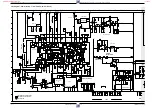
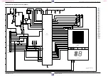
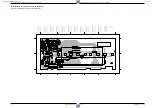
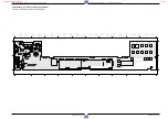
Platinenabbildungen und Schaltpläne / Layout of PCBs and Circuit Diagrams

Platinenabbildungen und Schaltpläne / Layout of PCBs and Circuit Diagrams

4 - 14

GRUNDIG Service-Technik

4 - 14

GRUNDIG Service-Technik

Chassisplatte – Standardton / Family Board – Standard Sound (AL)

33

34

0V

0V
4.8V

12V
0.3V

0V
5.3V

0V

0.6V

0V
0.7V

12V

10.5V

12V
9.8V

12V
9.8V

10.5V

12V

0V
10.4V

0V
0.1V

0.1V

0.6V

0.1V
10.4V

4.3V

1.4V

9.1V

12V

0.1V

0V

3.8V
3.7V

0.5V

3.8V

3.8V

3.6V

0.5V

0.1V

..V   MEASURED IN RECORD MODE

..V   MEASURED IN PLAYBACK MODE

1.5V

4.2V

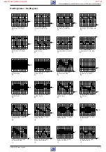
..O   OSCILLOGRAMS

Audio linear 9314

A.N. 9318

only for

Longplay

only for

Longplay

35

36

37

38

31

32

ERASE & BIAS OSCILLATOR

F8

F7

to Deck L8

to Deck L3

to VSIO

MEH2

MEH1

ARH

APH

AEH2

AEH1

CTL2

CTL1

to DE

BIAS

PB-LEVEL

to DE

to VSIO

7607  A 7

7606  C 8

7605  C 7

7604  B 6

7603  B 4

7602  E 7

7601  E10

5603  E 4

5602  G 3

5601  D12

3628  C 7

3627  A 8

3626  A 8

3625  B 8

3624  B 8

3623  C 7

3622  C 7

3621  C 8

3620  B 4

3619  C 4

3618  C 5

3617  C 6

3616  C12

3615  D12

3614  B13

3613  C13

3612  C13

3611  G14

3610  G14

3609  D 8

3608  D 8

3607  H13

3606  H11

3605  H11

3604  H11

3603  G11

3602  F10

3601  H 6

3600  G 5

2623  A 7

2622  E 3

2621  B 3

2620  C 4

2619  B 5

2618  C 4

2617  B 8

2616  C11

2615  C11

2614  D11

2613  B12

2612  C12

2611  D13

2610  G13

2609  H12

2608  H12

2607  G13

2606  G12

2605  H11

2604  G11

2603  G10

2602  G10

2601  G10

2600  H 6

162   E 2

161   H 2

4

5

1

6

7

8

9

10

11

12

13

14

15

16

2

3

H

G

F

K

E

D

C

B

A

J

I

H

G

F

K

E

D

C

B

A

J

I

4

5

1

6

7

8

9

10

11

12

13

14

15

16

2

3

2613

10n

100n

2607

100n

2606

1n5

2601

33n

2622

330p

2618

47n

2620

1n

2600

1n

2621

22n

2612

2610

100n

2602

2608

10n

2604

1n

2603

10n

2623

10k

3628

3k3

3627

47E

3626

33E

3625

3k3

3624

10k

3623

47k

3622

22k

3621

18k

3612

330E

3602

47k

3620

1E5

3619

56k

3601

22k

3617

33k

3611

47E

3600

100k

3609

1k

3616

470E

3615

15k

3614

12k

3610

9k1

3613

47k

3608

1M

3607

12k

3603

100E

3605

390k

3604

7607
BC328-40

7604
BC328-40

47u

2617

47u

2615

47u

2616

1u

2614

47u

2609

47u

2605

47u

261

1

47u

2619

161

1

2

3

4

5

6

7

BC848B

7605

BC848B

7606

BC848B

7602

+12A

+12A

7601

10

11

12

13

14

15

16

17

18

19

1

20

21

22

23

24

2

3

4

5

6

7

8

9

LA7282

EE/PB

PB

REC

EE

AMP

ALC

EP

LP

MUTE

MUTE

REC

EE

ALC

DET

POWER

MUTE

BUF

REC

EE/PB

CTL

MUTE

CTL

CTL

EP

EP

REC/EE

CTL

LP

EP

RIPPLE

FILTER

CTL

EQ

POWER

MUTE

AMP

CTL2

CTL1

IPALAL

MTA

LP

AMLP

IREC

REV

AMLR

330uH

5602

162

1

2

3

MEH

AEH

100k

3618

10k

3606

5603

1

2

3

4

6

audcoil

BC337-40

7603

CTL

R/P

10mH

5601

www.freeservicemanuals.info

It`s Free

Содержание GV 400

Страница 1: ...4005 MV 4105 GV 400 OST GV 411 OST RP 10 RT 130 RP 13 RT 230 PAL SECAM OST GV 400 77400 010 51 G MD 0200 RP 10 GV 402 77400 012 51 G MD 0900 RP 13 GV 410 77400 110 51 G MD 1400 RP 10 GV 412 77400 111 51 G MD 1900 RP 13 GV 430 77400 310 51 G MD 2600 RP 13 MV 4005 77400 044 51 M MD 0800 RP 10 MV 4105 77400 144 51 M MD 1700 RP 13 GV 400 OST 77400 013 51 G MD 5600 RT130 GV 411 OST 77400 112 51 G MD 57...

Страница 2: ...t MDCG1 4 17 Keyboard Control Unit MDCB1 4 19 Oscillograms 4 21 Drive Mechanism 5 1 5 10 Exploded Views and Spare Parts List 6 1 6 26 D Inhaltsverzeichnis Seite Allgemeiner Teil 1 1 1 38 Geräteübersicht 1 3 Meßgeräte Meßmittel 1 4 Technische Daten 1 4 Chip Technologie 1 5 Sicherheitsvorschriften 1 6 Sicherheitsbestimmungen 1 7 Abkürzungen 1 11 Bedienelemente 1 12 Servicehinweise 1 29 Servicetestpr...

Страница 3: ...t VSIO S P 4 12 27599 001 11 Standardton Standard Sound Audio Linear AL S P 4 14 27599 004 00 Kopfverstärker Head Amplifier 2 Kopf Head S P 4 15 27599 004 01 Kopfverstärker Head Amplifier 3 Kopf Head S P 4 15 27599 004 02 Kopfverstärker Head Amplifier 4 Kopf Head S P 4 16 27599 002 00 Bedieneinheit Keyboard Control Unit MDCG1 S P 4 17 27599 002 14 Bedieneinheit Keyboard Control Unit MDCB1 S P 4 19...

Страница 4: ...only available YoucanorderthesetestequipmentsfromtheServiceorganization We refer to you that these test equipments are already obtainable on the market Test cassette Part no 9 27540 1011 Colour test pattern with dropout recording 6 3kHz vertical full track recording alternating with 333Hz reference level every 3 minutes Test cassette HiFi Part no 9 27540 1016 Colour test pattern with dropout recor...

Страница 5: ...rwenden Sie nur einen Niedervoltlötkolben mit Temperatur regelung Die Löttemperatur sollte ca 240 C betragen max 300 C Halten Sie die Lötzeit so kurz wie möglich Belassen Sie CHIP Bauteile bis zur Bearbeitung in der Originalver packung Damit wird die Oxidation der Stirnkontakte vermieden Berühren Sie CHIP Bauteile nicht mit der bloßen Hand Auslöten von CHIP Bauteilen 1 Schritt CHIP Lötstelle mit S...

Страница 6: ...n against risk of fire replace only with same type of fuses CAUTION to reduce the risk of electric shock do not remove cover or back no user serviceable parts inside refer servicing to qualified service personnel Components to safety guidelines IEC U L Only use com ponents with the same specifications for replace ment By checking the leakage current and insulation resi stance ensure that the expos...

Страница 7: ...arts antenna sockets buttons screws etc made from metal or metal alloy The product is fault free if ILeak 1mA at UTest 220V Measuring time 1s Fig 2 We recommend that the measurements be carried out using the METRATESTER 4 Test equipment for checking electrical pro ducts to VDE 0701 ABB METRAWATT GmbH Thomas Mann Str 16 20 90471 Nürnberg If the safety of the product is not proved because a repair a...

Страница 8: ...dei fusibili I componenti che concorrono alla sicurezza dell apparecchio non possono essere nè danneggiati nè risultare visibilmente inadatti Questo vale soprattutto per isolamenti e parti isolate I cavi di rete e di collegamento vanno controllati prima dell utilizzo affinchè non presentino imperfezioni esteriori Controllare l isola mento E necessario controllare la sicurezza dei fermacavi e delle...

Страница 9: ...some installa tion and operation precautions which you should be particularly aware of Read Instructions All the safety and operating instructions should be read before the appliance is operated RetainInstructions The safety and operating instructionsshould be retained for future reference Heed Warnings All warnings on the appliance and in the opera ting instructions should be adhered to Follow In...

Страница 10: ...contre les charges statiques Des charges statiques peuvent se creér sur toutes les matières synthétiques à fort pouvoir isolant elles peuvent se transmettre au corps humain et le risque est d autant plus important si la personne porte des vêtements ou des chaussures en matière synthétique Les systèmes de protection dont sont équipées les entrées et sorties des circuits MOS n apportent qu une sécur...

Страница 11: ... DATD1 Daten IVC data IVC DE Ablaufsteuerung Deck Sequence Control Deckelec elektronik tronic ENVC Hüllkurven Komperator envelope comparator ESPBH Externe Wahl Wiedergabe ext select playback FFP V Impuls Testbild feature frame pulse FG Capstantacho capstan tacho FMPV FM Video Wiedergabe fm playback video FMR FM Aufnahmestrom fm rec current FMRV FM Videoaufnahme fm record video signal FTA Fädeltach...

Страница 12: ...Release the locking lugs F Fig 5 Withdraw the Keyboard Unit Unplug the connector if necessary Servicehinweise für Geräte mit dem Cassettenschacht links 1 Entfernen der Gehäuseteile Gehäuseoberteil 6 Schrauben A herausdrehen und Schraube A Fig 1 lösen Hinweis Die Schraube A ist zur VDE Sicherheit mit einer Sicherungsscheibe an der Haube befestigt und nicht abnehmbar Seitenteile des Gehäuseoberteils...

Страница 13: ...g lösen 3 2 Modulator ausbauen Chassisplatte ausbauen und Buchsenhalter abziehen Befestigungslaschen H lösen und Modulator auslöten Fig 6 Gegebenenfalls Steckverbindung lösen Fig 7 4 Netzteilbaustein ausbauen Rastnasen P ausrasten und Netzteilbaustein herausnehmen Fig 8 Gegebenenfalls Steckverbindungen lösen 4 1 Reparaturen im Netzteil Bei Reparaturen des Netzteilbausteins Trenntrafo benutzen Soll...

Страница 14: ...ed Discharge via the item being checked can damage components 8 Measured Values and Oscillograms The measured values given in the circuit diagrams and oscillograms are approximates U U T U 5 Removing the Head Amplifier Remove the Drive Mechanism Undo the screws T unplug the connectors and raise the Head Amplifier to remove it Fig 11 6 Removing the Drive Mechanism Release the locks R Fig 9 and S Fi...

Страница 15: ...Unit Release the locking lugs F Fig 5 Withdraw the Keyboard Unit Unplug the connector if necessary Servicehinweise für Geräte mit dem Cassettenschacht in der Mitte 1 Entfernen der Gehäuseteile Gehäuseoberteil 6 Schrauben A herausdrehen und Schraube A Fig 1 lösen Hinweis Die Schraube A ist zur VDE Sicherheit mit einer Sicherungsscheibe an der Haube befestigt und nicht abnehmbar Seitenteile des Gehä...

Страница 16: ...ung lösen 3 2 Modulator ausbauen Chassisplatte ausbauen und Buchsenhalter abziehen Befestigungslaschen H lösen und Modulator auslöten Fig 6 Gegebenenfalls Steckverbindung lösen Fig 6 Fig 7 4 Netzteilbaustein ausbauen Rastnasen P ausrasten und Netzteilbaustein herausnehmen Fig 6 Gegebenenfalls Steckverbindungen lösen 4 1 Reparaturen im Netzteil Bei Reparaturen des Netzteilbausteins Trenntrafo benut...

Страница 17: ...mage components 8 Measured Values and Oscillograms The measured values given in the circuit diagrams and oscillograms are approximates U U T U 5 Removing the Head Amplifier Remove the Family Board Remove the Drive Mechanism Undo the screws T unplug the connectors and raise the Head Amplifier to remove it Fig 10 6 Removing the Drive Mechanism Remove the Family Board Release the locks R Fig 8 and S ...

Страница 18: ...µC mask no START STOP PROG DATE START LP TODAY DECODER PDC VPS END Betriebsstundenzähler Operating hours meter Laufwerk Fehlerstatus Drive Mechanism error status Laufwerk Fehlercode Drive Mechanism error code Laufwerk Sensoren Drive Mechanism sensors Bedien µC Maskennr Keyboard Control µC mask no Bedien µC Version Keyboard Control µC version Laufwerk µC Maskennr Drive Mechanism µC mask no 1 2 Betr...

Страница 19: ...lers Für diese Überwachung werden die Tachoimpulse vom linken WTL und rechten WTR Wickelteller ausgewertet 3 3 Stillstand des Kopfscheibenmotors Zur Überwachung des Kopfscheibenmotors wird das PG FG Signal verwendet Dieses wird aus der EMK der nicht stromdurchflossenen Spulen des Kopfscheibenmotors abgeleitet und gibt die Position der Kopfscheibe an 3 4 Capstanmotorfehler Für diese Überwachung wir...

Страница 20: ... O Schneller Vorlauf Fast forward P Schneller Rücklauf Fast reverse Q Zeitlupe 1 16 Slow 1 16 R Zeitlupe 1 10 Slow 1 10 S Zeitlupe 1 6 Slow 1 6 T E E Betrieb E E Mode U Bereitschaft Schacht oben Standby eject V Index next W Index previous 4 Tape Deck Position and Function of the Init Switch The diagram shows the function of the Init switch dependent on the tape deck position For this the number of...

Страница 21: ...s The fault is stored in the EEPROM and is saved even if the VCR is disconnected from the mains Calling the Continuous Operation Test Insert a cassette Enter the test programme by simultaneously pressing the STOP button on the remote control and the Jbutton on the video recorder for at least 5 seconds Start the continuous operation test by pressing the button REC J or F The video recorder is then ...

Страница 22: ...he transformer which is fed tothesecondarywindingsinthecut offphase TheIC7110controlsthe transferred energy by the switch on period of T7135 so that the secondary voltages are held constant largely independent of mains voltage and load variations The required control information is produ ced via the optocoupler see above In addition zero transition detection is carried out on IC7110 8 by the infor...

Страница 23: ...g function groups 2 1 1 Reset 2 1 2 Threading motor control cassette compartment threading mechanism 2 1 3 Winding tachopulse processing 2 1 4 Beginning of tape end of tape detection 2 1 5 Head servo control 2 1 6 Tape servo control 2 1 7 Tracking autotracking 2 1 8 EEPROM 2 1 1 Reset When connecting the video recorder to the mains the IC7411 gener ates the switch on reset pulse with the reset cap...

Страница 24: ...oftware Abgleichwerte Die Datenübertragung erfolgt über den I2 C Bus SDA SCL On IC7410 31 the µC feeds out a pulse width modulated square wave signal REEL containing information on the speed and the phase This signal is fed via the plug contact F4 6 to the headwheel motor driver IC7301 located in the head amplifier and is used as a control voltage 2 1 6 Tape Servo Control The capstan motor is a th...

Страница 25: ...nd ein Band 1 Pin 13 LOW Pin 14 LOW Band 3 Pin 13 LOW Pin 14 HIGH UHF Pin 13 HIGH Pin 14 LOW 2 2 Family Board Frontend FV Signal Processing The Frontend has the function of amplifying and demodulating the IF signal fed in from the tuner The resulting signals are the CCVS signal and the audio signal From the tuner contact 17 the IF signal passes through the surface acoustic wave filter F1721 which ...

Страница 26: ...to Pin 3 of the IC7051 The externally connected components of the deemphasis stage are the R3037 C2019 and C2020 Adjustment of the playback amplitude 2 3 Chassisplatte Video Chroma VSIO Eingangswahlschalter IC7551 Das FBAS Eingangssignal von der Empfangseinheit VFV bzw von der EURO AV Buchse SCART1 wird freigegeben über die Gleich spannung 12A sowie den Schalt IC7551 14 12 Anschlie ßend gelangt es...

Страница 27: ...e Funktion eines Kammfilters besteht darin in einem Schaltungs zweig CF873 4 das jeweilige Signal bei PAL um 2 Zeilen zu is possible with the control R3039 Y PB LEVEL via IC7051 2 Afterwards the CVS signal is passed on via a phase compensation stage T7006 R3033 C2095 L5025 an amplifier stage T7007 and C2012 to IC7051 4 In IC7051 the signal is clamped CLAMP before the A W switch and after the 3 5MH...

Страница 28: ...ator frequency 4 43361MHz The result is the subcarrier frequency of 5 06MHz The subcarrier passes through an internal 5 06MHz bandpass and is then fed to the main converter MAIN CONV Playback NTSC PAL Onplaybackuseismadeofthequartzfrequency Q1601 4 43361MHz of the free running XO quartz oscillator as a reference and the VCO oscillator After reconversion of the chroma signal from 627kHz PAL or 629k...

Страница 29: ...neinheit MDC Der Mikrocomputer IC7101 ist das Kernstück der Bedieneinheit und erfüllt folgende Aufgaben mit den entsprechenden Funktionsgruppen 3 1 Auswertung der Tastaturmatrix 3 2 Decodierung der Fernbedienbefehle vom Infrarot Empfänger IC7103 3 3 Quarz Uhr 3 4 Integriertes RAM zum Speichern der Timer Daten 3 5 Ansteuerung des Displays 3 6 Bidirektionale serielle Schnittstelle zum Datenaustausch...

Страница 30: ...stausch der Chassisplatte oder der Kopfscheibe Abgleich Nr 1 des IC7412 Abgleich Nr 1 2 2 Empfangseinheit FV Abgleich Nr 3 Abgleich Vorbereitung Abgleichvorgang Abgleich Vorbereitung Abgleichvorgang 1 Kopfrad Lagengeber Testcassette einlegen Service Funktion aufrufen Gleichzeitig für ca 5sec auf dem Fernbediengeber die Taste STOP und am Gerät die Taste e drücken Gleichzeitig auf dem Fernbediengebe...

Страница 31: ...requenzhub Synchronwert R3018 2 2 Weißwert R3020 3 Aufsprechstrom 3 1 Y Aufsprech strom R3099 3 2 Chroma Aufsprechstrom R3096 4 Wiedergabe amplitude R3039 Weißtestbild einspeisen 100 Weiß Oszilloskop IC7501 4 EE Betrieb Kein Antennensignal einspeisen Aufnahme Frequenzzähler KopfverstärkerTP1 Videocurrenttestpin Abgleich 1 EE Pegel und 2 1 Frequenzhub Synchronwert kontrollieren Weißtestbild einspei...

Страница 32: ...instellen NF Millivoltmeter R3600 Aufnahme FBAS Signal über EURO AV Buchse Kontakt 20 ein speisen Audio Signal 200mVeff 480mVss vom Tongenerator an der EURO AV Buchse Kontakte 2 oder 6 einspeisen Aufnahme mit jeweils ca 1 Minute 400Hz und 8kHz Ton durchführen Anschließend diese Aufnahme wiedergeben NF Millivoltmeter Oszilloskop an EURO AV Buchse Kontakt 1 oder 3 Tongenerator 1kHz 0 7Veff EURO AV B...

Страница 33: ...ids Test cassette Service work after changing the Family Board or Headwheel Adjustment no 1 IC7412 Adjustment no 1 2 2 Frontend FV Adjustment no 3 Adjustment Preparation Adjustment Procedure 1 Headwheel Position Indicator Load a test cassette Call up the service function Press the STOP button on the remote control handset and the 2 button on the recorder simultaneously for approx 5s Press the 2 bu...

Страница 34: ... DE Adjustment no 1 1 EE Level R3010 2 1 Frequency Deviation Sync Value R3018 2 2 White Value R3020 3 Record Current 3 1 Y Record Voltage R3099 3 2 Chroma Record Current R3096 4 Playback Amplitude R3039 Set amplitude with R3010 E E LEVEL to 0 5VPP 0 02V The voltage at the AV socket 1 contact 19 must be 1 9Vpp 0 1V SetfrequencycounterwithR3018 SYNCFREQ to3 8MHz 10kHz Set frequency counter with R302...

Страница 35: ...voltmeter R3600 Record Feed in a CCVS signal via EURO AV socket contact 20 Feed an audio signal of 200mVrms 480mVpp from the AF generator to the EURO AV socket contact 2 or 6 Make a recording of 400Hz and 8kHz each of 1 min at least Afterwards play back these recordings Connect an AF millivoltmeter oscilloscope to EURO AV socket pins 1 or 3 AF generator 1kHz 0 7Vrms EURO AV socket contact 2 or 6 A...

Страница 36: ...V GNDA FMRV HP1 HSC REV 5A FMPV GNDA ENVC IFEO TRIV 10 9 8 7 6 5 4 3 2 1 PG FG 14M2 GNDD GNDM2 5D REEL 6 5 4 3 2 1 GNDD 14 9 CREV CAP FG GNDM1 SVHS TAS INIT LED WTR FTA RECP WTL 5D TAE 16 15 14 13 12 11 10 9 8 7 6 5 4 3 2 1 TMO1 TMO2 1 2 13 1 2 3 4 5 6 7 8 9 10 11 12 1 2 3 1 2 3 4 5 6 7 MEH1 MEH2 2 1 Component side Family Board Display Control GNDD 14 9 CREV CAP FG GNDM1 SVHS TAS INIT LED WTR FTA ...

Страница 37: ...ut of PCBs and Circuit Diagrams Platinenabbildungen und Schaltpläne Layout of PCBs and Circuit Diagrams 4 2 GRUNDIG Service Technik 4 2 GRUNDIG Service Technik Blockschaltplan Block Circuit Diagram Analog www freeservicemanuals info It s Free ...

Страница 38: ...t of PCBs and Circuit Diagrams Platinenabbildungen und Schaltpläne Layout of PCBs and Circuit Diagrams GRUNDIG Service Technik 4 3 GRUNDIG Service Technik 4 3 Blockschaltplan Block Circuit Diagram Digital www freeservicemanuals info It s Free ...

Страница 39: ...DO NOT OPERATE WITHOUT CASE ISOLATION TRANSFORMER WHEN SERVICING HOT CIRCUIT BE CAREFUL AND USE AN 2112 68u 385V 2114 47u 25V 5103 2x47m Netzteil Power Supply MSM1 Primärseite mit SPH4690 Primary Side with SPH4690 3 1 0 3 1 0 3 3 8 5 6 0 8 2 0 3 1 7 0 5 9 1 0 2 MSM1 1 1 A B A B 1 2 3 4 5 1 2 3 4 5 1 1 0 1 A 5 2 1 0 1 A 4 2 1 0 3 A 4 2 1 0 5 B 5 2 1 0 7 B 4 2 1 1 2 A 4 2 1 1 3 A 2 2 1 1 4 B 3 2 1 1...

Страница 40: ...15 16 2 3 H G F K E D C B A J I H G F K E D C B A J I 4 5 1 6 7 8 9 10 11 12 13 14 15 16 2 3 1N4148 6116 1N5062 6111 1N5062 6112 1N5062 6110 1N5062 6113 BYD73C 6201 MUR410 6203 MUR410 6204 BYD73C 6206 1N4148 6115 SB340 6210 1N5062 6114 BUZ90A 7135 TDA4605 3 7110 1 2 3 4 5 6 7 8 tda4605 VSt generator V2B VGA ref reproducer comparator Vu amplifier typ 3V VG min voltage protection regulating low volt...

Страница 41: ... 9063 B 3 9064 C 8 9065 A 5 9066 A 5 9067 A 5 9068 B 5 9069 B 5 9070 B 5 9071 B 5 9072 B 5 9073 B 5 9074 B 5 9075 B 5 9077 A 5 9078 B 5 9079 B 2 9080 C 2 9081 C 5 9100 C 7 9101 C 8 9102 C 8 9103 C 6 9104 C 8 9105 C 8 9106 C 7 9107 C 8 9108 C 8 9109 C 8 9110 C 8 9111 C 8 9112 C 7 9113 C 7 9114 C 6 9115 C 7 9116 C 7 9117 C 7 9118 C 7 9119 C 7 9120 C 7 9121 C 6 9122 C 5 9123 B 6 9124 B 6 9125 B 6 912...

Страница 42: ...1 3901 B 2 3902 C 1 3903 B 3 3904 C 4 3905 A 3 3950 B 1 3951 A 4 3976 C 6 3977 B 7 3978 B 6 3979 B 8 3980 B 8 3981 B 8 3982 B 7 3983 B 6 3984 A 7 7000 B 2 7001 B 3 7004 A 4 7006 A 4 7007 A 4 7016 B 3 7017 B 4 7018 B 5 7019 B 4 7020 B 5 7025 C 3 7026 C 3 7029 C 3 7030 C 3 7031 A 3 7032 A 3 7036 B 4 7037 A 4 7038 A 5 7053 A 4 7403 B 6 7404 C 8 7406 C 6 7407 C 6 7500 C 1 7501 C 3 7502 B 2 7506 C 1 76...

Страница 43: ... 2417 L 7 2416 L11 2415 L 5 2414 J 7 2413 J 6 2412 J 5 2411 I 5 2410 H 7 2409 F 6 2408 E 5 2407 D 6 2406 L14 2405 L15 2404 H12 2403 B14 2402 B16 2401 B10 2400 B11 145 D 2 144 H 1 143 L 1 142 P 4 141 P 8 1402 N11 1401 L15 1400 O 9 7412 L18 7411 L 8 7410 F15 7408 L22 7407 M22 7406 N21 4 5 6 1 7 8 9 10 11 12 13 14 15 16 17 2 18 19 20 21 22 23 3 M L K P J I H G F E D C B A O N M L K P J I H G F E D C ...

Страница 44: ...3 B 8 1002 E 7 1001 J 5 0007 K 2 0005 H10 0004 I 3 4 5 6 7 1 8 9 10 2 3 M L P K J I H G F E D C B A O N M L P K J I H G F E D C B A O N 4 5 6 7 1 8 9 10 2 3 7 8 10 9 11 12 13 14 15 16 6 5 4 3 2 1 0005 1001 10 1 2 3 4 5 6 7 8 9 11 12 13 14 15 16 STRIP 1006 10 1 2 3 4 5 6 7 8 9 11 12 13 14 STRIP 1002 10 1 2 3 4 5 6 7 8 9 STRIP 1004 1 2 3 4 5 6 7 8 STRIP 1007 1 2 3 4 STRIP 1003 1 2 3 4 STRIP 1005 1 2...

Страница 45: ...4512 8203 101 74512 7102 1007 2 1 1 1006 2 0003 SW3 SVHS 0004 SW2 INIT 3600 6104 7105 7104 3601 3602 1 2 1005 6103 7105 6104 9001 SW1 RECP 3500 3502 3501 1 1004 2 1 2 1003 7106 3401 1 2 1002 9002 2001 7101 1001 1 2 0007 3103 3200 3300 9004 3201 3203 3202 7100 3104 3100 9005 L2 B C E CON3 E C B TAE WTL FTA WTR TAS 9011 3105 9007 0005 www freeservicemanuals info It s Free ...

Страница 46: ...24 F13 1723 E13 1722 E12 1721 C 7 1720 B 4 1701 K 2 7714 E 7 7713 E 6 7712 D 7 7711 G 1 7710 F 1 7709 F 3 4 5 1 6 7 8 9 10 11 12 13 14 15 16 2 3 H G F K E D C B A J I H G F K E D C B A J I 4 5 1 6 7 8 9 10 11 12 13 14 15 16 2 3 1k2 3746 470E 3757 18k 3750 4k7 3751 470E 3752 1k 3753 1k2 3747 1k 3744 4k7 3743 18k 3742 3k9 3741 22k 3739 470E 3740 330E 3754 10E 3755 560k 3708 560E 3731 330E 3730 3728 ...

Страница 47: ... 5VPB1 5VL2 5VL2 5VL2 5VL2 5VL2 5VL2 5VL2 5VL2 5VPB 5VL2 7V 7051 LA 7191 DO STOP FM K LPF SUB LIM DEMOD DOUBLE MAIN ROTARY DE EMPH SHIFT 1 2fH LP SP AMP FM MOD VIDEO INSERT FBC LIM CORR 6dB ENH VCC1 DETAIL 6dB P R P R NL BGP EMPH LPF DOC N CHROMA 6dB AGC W D CLIP VIDEO MAIN EMPH CLAMP DET AGC DELAY LPF CLAMP DO 3 5MHz DET CLAMP CLIP o ID DE EMPH BGP P 5 06M BPF PAL VCA CLAMP BGP ID SW P R PROTECT ...

Страница 48: ...2 E31 6501 B31 6004 M 4 6002 J 2 6001 K10 5501 M30 5025 L 3 5024 G19 5023 G18 5022 N27 5021 N26 5017 K 2 5016 N10 5015 N11 9011 N17 5014 L14 5013 C16 5012 D17 5011 B17 5010 B17 5009 D19 5008 B19 5006 B12 5005 B 7 5004 C 5 7551 A27 5003 D 5 5002 D 4 3951 I 1 3905 K13 3902 H29 3521 N31 3520 F28 3517 N25 3516 N30 3515 B31 7551 E27 3514 B26 3513 C25 3512 C28 3511 C29 3510 C30 3509 C30 3508 D31 3507 D3...

Страница 49: ...2622 E 3 2621 B 3 2620 C 4 2619 B 5 2618 C 4 2617 B 8 2616 C11 2615 C11 2614 D11 2613 B12 2612 C12 2611 D13 2610 G13 2609 H12 2608 H12 2607 G13 2606 G12 2605 H11 2604 G11 2603 G10 2602 G10 2601 G10 2600 H 6 162 E 2 161 H 2 4 5 1 6 7 8 9 10 11 12 13 14 15 16 2 3 H G F K E D C B A J I H G F K E D C B A J I 4 5 1 6 7 8 9 10 11 12 13 14 15 16 2 3 2613 10n 100n 2607 100n 2606 1n5 2601 33n 2622 330p 261...

Страница 50: ...08 B 1 2109 B 1 2110 B 1 2112 B 1 2301 C 1 2302 C 1 2306 C 1 2307 C 1 2308 C 1 2309 C 1 2310 C 1 2311 C 1 2312 C 1 2313 C 1 2315 C 1 2316 B 1 2317 C 1 2318 C 1 2319 C 1 2400 A 1 2401 A 1 2402 A 1 2403 A 1 2404 A 1 2405 A 1 2406 A 1 2407 A 1 2409 A 1 2410 A 1 2413 A 1 2414 B 1 2420 A 1 3101 C 1 3102 C 1 3103 C 1 3104 C 1 3105 C 1 3107 B 1 3301 C 1 3302 C 1 3303 C 1 3304 C 1 3305 C 1 3306 C 1 3307 C...

Страница 51: ...6 B 1 2317 C 1 2318 C 1 2319 C 1 3001 A 1 3002 A 1 3003 A 1 3004 A 1 3005 A 1 3008 A 1 3010 A 1 3011 B 1 3012 B 1 3015 B 1 3024 B 1 3025 B 1 3026 B 1 3101 C 1 3102 C 1 3103 C 1 3104 C 1 3105 C 1 3107 B 1 3201 B 1 3202 B 1 3203 B 1 3204 B 1 3205 B 1 3206 B 1 3301 C 1 3302 C 1 3303 C 1 3304 C 1 3305 C 1 3306 C 1 3307 C 1 3308 C 1 3309 C 1 3310 C 1 3311 C 1 3312 C 1 3313 C 1 3801 A 1 3803 A 1 3804 A ...

Страница 52: ... 1b 1a 1G PROG DATE F1_ P9 P8 P7 P6 P5 P4 P3 P2 P1 5G P14 P13 P12 P11 P10 P15 F1 P16 F2_ 6G F2 7G 8G PDC TIMER 1G REC VPS PAL LP SEC 2G 8G 10g 10f 10e 10d 10c 10b 10a 10n 10p 10r 10h 10j 10m 10k 9n 9p 9r 9h 9j 9m 9k 7G 9g 9f 9e 9d 9c 9b 9a 8n 8p 8r 8h 8j 8m 8k 8g 8f 8e 8d 8c 8b 8a 6G 3G 7n 7p 7r 7h 7j 7m 7k 7g 7f 7e 7d 7c 7b 7a 5G STOP START 4G 6e 6d 6c 6b 6a 5g 5f 5e 5d 5c 5b 5a 6f 6g 3g 3b 3a 3G...

Страница 53: ...2 3302 B 1 5000 A 1 6010 A 2 6011 A 3 6012 B 2 6031 A 1 6032 A 1 6050 B 1 6099 A 1 7030 A 1 7031 A 1 7102 B 3 7103 B 1 9001 B 1 9002 A 1 9003 A 1 9004 A 1 9005 B 2 9006 A 1 9007 B 1 9008 A 1 9010 A 4 9011 A 4 9012 A 4 9013 A 3 9014 A 3 9015 B 3 9016 B 2 9017 A 3 9018 B 2 9019 B 1 DOW N B 2 EJ ECT B 5 PLAY B 3 REC B 2 REW B 4 STBY B 4 STI LL B 4 STOP B 5 UP B 1 W I ND B 2 bar c ode A 5 9006 9007 20...

Страница 54: ... 2G PDC j1 j2 F2_ 1G a1 b1 f1 e2 g1 1G c2 b2 d1 e1 c1 d2 g2 f2 a2 DECO F2 P9 P8 P7 P6 P5 P4 P3 P2 P1 P14 P13 P12 P11 P10 P15 P16 4G c2 14G g2 f1 b1 a1 f2 b2 c1 g1 e2 a2 14G d2 d1 e1 END c2 g2 9G e2 f2 b2 d2 a2 d1 e1 c1 13G g1 f1 b1 a1 START k b e m g f h n c a r d LP 12G 13G j1 j2 r n e c f b k d m h g a 11G j1 j2 12G b k g f n e m r h a c d 10G j1 j2 11G m a r n c g k h e f b d 9G j1 j2 10G 9G g ...

Страница 55: ...3053 B 5 3300 A 1 3301 B 1 3302 A 2 5000 A 2 6010 B 7 6011 B 7 6012 B 7 6031 B 1 6032 B 1 6050 A 1 6099 A 2 7030 B 1 7031 B 1 7102 B 5 7103 B 3 9001 A 2 9002 A 1 9003 A 1 9004 A 1 9005 A 1 9006 A 1 9007 A 1 9008 A 1 9009 A 1 9010 B 5 9011 B 8 9012 B 2 9013 B 2 9014 B 1 9015 B 2 9016 A 2 9017 A 1 9022 B 1 9023 B 1 DC1 A 1 bar c ode B 8 3032 3 0 3 7 6 0 3 1 7 0 3 0 2037 7031 3034 2030 2031 6032 9002...

Страница 56: ...0 mV Div 20 us Div IC 7051 Pin 39 PB 0V A DC 0 5 V Div 10 us Div IC 7051 Pin 34 VSB PB 0V A DC 1 0 V Div 20 us Div IC 7051 Pin 32 CSYNC REC 2V A AC 50 mV Div 5 ms Div IC 7051 Pin 27 PB 2V A DC 0 5 V Div 10 us Div IC 7051 Pin 25 PB 2 5V A AC 0 1 V Div 10 us Div IC 7051 Pin 3 PB 2V A DC 0 2 V Div 10 us Div IC 7051 Pin 5 REC 2V A AC 0 1 V Div 10 us Div IC 7051 Pin 10 PB 2V A AC 0 1 V Div 10 us Div IC...

Страница 57: ...onnector F4 1 PG FG 1 PB 0V A DC 0 5 V Div 0 5 ms Div Connector F3 13 LED 2 PB 0V A DC 0 5 V Div 2 ms Div Connector F3 12 WTR Wind 3 0V PB 0V A DC 1 V Div 2 ms Div Connector F3 11 FTA Threading 4 PB 0V A DC 0 5 V Div 2 ms Div Connector F3 9 WTL Wind 5 PB 0V A DC 0 2 V Div 10 us Div Connector F3 3 CAP 6 PB 3V A AC 0 5 V Div 0 2 ms Div Connector F3 2 FG 7 PB 0V A DC 1 V Div 10 ms Div IC 7411 Pin 2 C...

Страница 58: ...räzisionsantrieb der Kopfscheibe Direktantrieb der Capstanwelle und der Wickelteller Motor für die Cassettenschachtbewegung und das Ein Ausfädeln des Bandes Besondere Merkmale sind Quickstart Kurze Umspulzeit Automatische Reinigung der Videoköpfe durch Reinigungsrolle Um zuverlässige Reparaturen zu garantieren wurde eine Anzahl von ServiceKitsentwickelt DieseKitsenthaltenallewesentlichenService te...

Страница 59: ...amount Turn the threading motor counterclockwise Fig 4 until the cassette compartment is down 1 1 Laufwerkausbau Arretierungen R Fig 1 und S Fig 2 des Cassettenschachtes lösen und diesen dabei so weit nach innen schieben bis die Schrauben U Fig 3 zugänglich sind Schrauben U entfernen Fig 3 und gegebenenfalls Steckverbin dungen zur Elektronik lösen 1 2 Absenken des Cassettenschachtes von Hand ohne ...

Страница 60: ...en bis das Band komplett in der Cassette aufgewickelt ist 2 1 Zahnräder und Hebelpositionen Laufwerk in Stellung ausgefädelt Cassettenschacht unten Nachfolgend sind die markierten und gerichtet einzubauenden Teile der Ober und Unterseite im Detail dargestellt Fig 5 Fig 6 Laufwerkoberseite Cassettenschacht abgenommen Bremse rechts Main brake right Pos 10K Triggerschieber Trigger slider Pos 4K Schwe...

Страница 61: ...e locks R Fig 1 and S Fig 2 of the cassette compartment and move it inwards until the cassette compartment lowers by a small amount Turn the driving gear of the threading motor in the threading direction Fig 4 until the gearwheel Pos 103H Fig 7 disengages Release the bracket Pos 102H from the shaft of gearwheel A Fig 7 Unscrew the 4 screws A Fig 6 on the underside of the cassette compartment Remov...

Страница 62: ...tor vorne und hinten eingerastet ist 2 3 Headwheel Removal Do not touch the headwheel without wearing the nylon gloves Insert the reference pin C delivered with each service headwheel into the hole on the bottom of the scanner motor and turn the headwheel until the pin locks into the hole of the rotor Fig 8 Loosen the fixing screw A of the headwheel by 2 3 turns and pull off the headwheel from the...

Страница 63: ...m the guide After replacing the threading roller unit right check and if necessary readjust the tape transport chapter 3 1 39 2 1 Fig 13 Fig 12 Capstanmotor Chassis 41G 46A 38 Fig 14 Pinzette Tweezers 2 6 Capstanmotor Pos 127 Laufwerk in Stellung Eject bringen Antriebsriemen Pos 126 entfernen Sensorplatine über Capstanmotor lösen und hochklappen 3 Befestigungsschrauben auf der Oberseite entfernen ...

Страница 64: ...asily be released and removed Reassembly is carried out by snapping the snap hooks into place and inserting the rivet B 2 9 Fädelschlitten links Pos 23 Laufwerk in Position Eject bringen Feder Pos 11 aushaken damit der Bandzugfühler nicht vor gespannt ist An der Unterseite des Laufwerks die Sensorplatine teilweise aus hängen und den Hebel Pos 112 entfernen Mit einer Pinzette die beiden Schnapphake...

Страница 65: ...V as straight and flat as possible Fig 18 23 16 33 34 26 29F 31F 20ms Trigger CTL TRIV Videokopf Video head Spurbild Video Track Diagram Band Tape Ansicht von der Bandoberseite View to foil side Videospur Video track 3 1 1 Fädelschlitten links und rechts Vor dem Einstellen der Fädelschlitten links und rechts muß der X Abstand Kap 3 2 richtig eingestellt sein Ist dies nicht der Fall können folgende...

Страница 66: ...fes getauscht wurden müssen die Einstellungen der Kapitel 3 1 1 und 3 1 2 gegebenenfalls mehrmals durchgeführt werden 3 2 Einstellung des X Abstandes Vor dieser Einstellung muß die Testcassette erneut eingelegt wer den von Eject Stellung starten Das Servicetestprogramm aufru fen der Trackingwert geht dadurch in die Mittelstellung und die Taste J drücken Den Schwarz Weiß Teil der Testcassette wiede...

Страница 67: ...gf cm Bandzugfühlhebel Tension arm linke innere Führungskante Guiding left Bandzugjustierung Tape tension adjustment Bremsbandjustierung Brake band adjustment Ø 0 5mm Fig 20 Fig 21 Pos 41G Pos 45A Fig 23 Fig 22 3 3 Bremsbandeinstellung Cassettenschacht absenken Kap 1 2 Riemenscheibe des Fädel motors Fig 4 in Drehrichtung Einfädeln drehen bis das Kurven rad in der abgebildeten Stellung Fig 22 ist M...

Страница 68: ...5 24B 23 26 21G 22G 140 20J 20aJ 13J 19J 18J 17J 16 25B 27B 28G 31F 32F 30F 29F 18J 15 14K 6K 9K 7K 6K 10K 3K 4K 11 12 2 5K 150 48A 44AB 43K 42K 45A 36 37 38 39 40G 41G 46A 47 2 1 13J 170 49G Öl Oil Sach Nr Part No 75988 002 35 Fett Grease Sach Nr Part No 75988 002 36 Isopropanol Fusselfreies Tuch Fibrefree Tissue www freeservicemanuals info It s Free ...

Страница 69: ...2 114 119E 120E 108E 109E 117 I 116 I 115 121E 113B 118 112E 111B 110E 106 107E 105H 104H 101E 102H 127 128G 129 124E 123E 122E 125E 103H 126 Fett Grease Sach Nr Part No 75988 002 36 Isopropanol Fusselfreies Tuch Fibrefree Tissue www freeservicemanuals info It s Free ...

Страница 70: ...xploded Views GRUNDIG Service Technik 6 3 3 0008 000 0008 000 0008 000 0007 000 0004 000 0006 002 0006 001 0006 000 0005 000 0060 000 0050 000 0002 000 0003 000 0040 000 0070 000 0001 000 www freeservicemanuals info It s Free ...

Страница 71: ...xploded Views 6 4 GRUNDIG Service Technik 3 0008 000 0008 000 0008 000 0007 000 0004 000 0006 002 0006 001 0006 000 0005 000 0060 000 0050 000 0002 000 0003 000 0040 000 0001 000 0070 000 www freeservicemanuals info It s Free ...

Страница 72: ... INSTRUCTION MANUAL X SIEHE GESONDERTE E LISTE X SEE SEPARATE PARTS LIST SACH NR PART NO 77400 012 51 BESTELL NR ORDER NO G MD 0900 Ersatzteilliste List of spare parts POS ABB SACHNUMMER ANZ NR NR POS FIG PART NUMBER QUA NO NO BEZEICHNUNG DESCRIPTION D GB 6 93 GV 400 SACH NR PART NO 77400 010 51 BESTELL NR ORDER NO G MD 0200 0001 000 75988 000 01 RAHMEN FRAME 0002 000 75988 000 02 FUSS FOOT 0003 0...

Страница 73: ...FLEXIBLE CABLE L6 1911 75988 002 71 BEDIENUNGSANLEITUNG INSTRUCTION MANUAL X SIEHE GESONDERTE E LISTE X SEE SEPARATE PARTS LIST Ersatzteilliste List of spare parts POS ABB SACHNUMMER ANZ NR NR POS FIG PART NUMBER QUA NO NO BEZEICHNUNG DESCRIPTION D GB SACH NR PART NO 77400 111 51 BESTELL NR ORDER NO G MD 1900 0001 000 75988 000 01 RAHMEN FRAME 0002 000 75988 000 02 FUSS FOOT 0003 000 75988 000 03 ...

Страница 74: ...XIBLE CABLE L6 1911 75988 003 01 BEDIENUNGSANLEITUNG INSTRUCTION MANUAL X SIEHE GESONDERTE E LISTE X SEE SEPARATE PARTS LIST Ersatzteilliste List of spare parts POS ABB SACHNUMMER ANZ NR NR POS FIG PART NUMBER QUA NO NO BEZEICHNUNG DESCRIPTION D GB 7 93 MV 4005 SACH NR PART NO 77400 044 51 BESTELL NR ORDER NO M MD 0800 0001 000 75988 000 01 RAHMEN FRAME 0002 000 75988 000 02 FUSS FOOT 0003 000 759...

Страница 75: ... L6 1911 FLEXIBLE CABLE L6 1911 75988 002 91 BEDIENUNGSANLEITUNG INSTRUCTION MANUAL X SIEHE GESONDERTE E LISTE X SEE SEPARATE PARTS LIST Ersatzteilliste List of spare parts POS ABB SACHNUMMER ANZ NR NR POS FIG PART NUMBER QUA NO NO BEZEICHNUNG DESCRIPTION D GB 7 93 GV 400 OST 0001 000 75988 003 10 RAHMEN FRAME 0002 000 75988 000 02 FUSS FOOT 0003 000 75988 003 11 BODEN BOTTOM 0004 000 8114 990 022...

Страница 76: ...RING 2X 0010 000 1 75988 001 32 K BREMSE RECHTS MAIN BRAKE RIGHT 0011 000 1 75988 001 03 ZUGFEDER TENSION SPRING 0012 000 1 75988 001 04 KLINKE TENSION CRANK 0013 000 1 75988 001 31 J SCHEIBE SLIP RING 0014 000 1 75988 001 32 K BREMSBAND BRAKE TAPE 0015 000 1 75988 001 05 BANDZUGFUEHLER TAPE TENSION ARM 0016 000 1 75988 001 06 LOESCHKOPF KPL ERASE HEAD ASSY 0017 000 1 75988 001 31 J SCHWENKRAD SWI...

Страница 77: ...PFVERSTAERKER LHA 4 2 1 HEAD AMPLIFIER LHA 4 2 1 75988 001 24 KIT A KIT A 75988 001 25 KIT B KIT B 75988 001 26 KIT E KIT E 75988 001 27 KIT F KIT F 75988 001 28 KIT G KIT G 75988 001 29 KIT H KIT H 75988 001 30 KIT I KIT I 75988 001 31 KIT J KIT J 75988 001 32 KIT K KIT K OPTIONAL KIT POS ABB SACHNUMMER ANZ NR NR POS FIG PART NUMBER QUA NO NO BEZEICHNUNG DESCRIPTION Ersatzteilliste List of spare ...

Страница 78: ...3 KEFQ 0805 82PF 5 C 2071 8672 160 130 KEFQ 0805 47PF 5 C 2072 8672 167 246 KEFQ 0805 1000PF 10 C 2079 75988 001 36 SMD KONDENS 10N C 2080 8672 167 246 KEFQ 0805 1000PF 10 C 2087 8672 160 140 KEFQ 0805 330PF 5 C 2088 75988 001 42 SMD KONDENS 100N C1206 C 2090 75988 001 42 SMD KONDENS 100N C1206 C 2095 8672 160 130 KEFQ 0805 47PF 5 C 2096 8672 160 130 KEFQ 0805 47PF 5 C 2099 8672 167 246 KEFQ 0805 ...

Страница 79: ...0 OHM 5 R 3008 8706 100 105 R CHIP 0805 22 KOHM 5 R 3010 75988 001 53 ESTR 4 7 KOHM R 3017 8706 100 097 R CHIP 0805 10 KOHM 5 R 3018 75988 001 53 ESTR 4 7 KOHM R 3019 8706 100 091 R CHIP 0805 5 6 KOHM 5 R 3020 75988 001 53 ESTR 4 7 KOHM R 3021 75988 001 54 CHIP WIDERST 2 7KOHM R 3022 75988 001 55 CHIP WIDERST 820 OHM R 3023 8706 100 073 R CHIP 0805 1 KOHM 5 R 3025 8706 100 121 R CHIP 0805 100 KOHM...

Страница 80: ...OHM 5 R 3733 8706 100 081 R CHIP 0805 2 2 KOHM 5 R 3735 8706 100 113 R CHIP 0805 47 KOHM 5 R 3736 8706 100 113 R CHIP 0805 47 KOHM 5 R 3737 8706 100 113 R CHIP 0805 47 KOHM 5 R 3738 8706 100 113 R CHIP 0805 47 KOHM 5 R 3739 8706 100 105 R CHIP 0805 22 KOHM 5 R 3741 75988 001 56 CHIP WIDERST 3 9KOHM R 3742 8706 100 103 R CHIP 0805 18 KOHM 5 R 3743 8706 100 089 R CHIP 0805 4 7 KOHM 5 R 3744 8706 100...

Страница 81: ...ESCRIPTION SACHNUMMER PART NUMBER POS NR POS NO D GB POS ABB SACHNUMMER ANZ NR NR POS FIG PART NUMBER QUA NO NO BEZEICHNUNG DESCRIPTION Ersatzteilliste List of spare parts D GB BEZEICHNUNG DESCRIPTION SACHNUMMER PART NUMBER POS NR POS NO D GB BEZEICHNUNG DESCRIPTION SACHNUMMER PART NUMBER POS NR POS NO D GB SACH NR PART NO 27599 001 11 7 93 CHASSISPLATTE MFB FAMILY BOARD MFB C 2082 75988 001 50 EL...

Страница 82: ...ERST 1 8W 220 OHM R 3029 75988 000 74 WIDERST 1 8W 10KOHM PM5 R 3030 75988 002 15 WIDERST 1 8W 22KOHM R 3031 75988 000 76 WIDERST 1 8W 4 7KOHM PM5 R 3032 75988 000 73 WIDERST 1 8W 1KOHM PM5 R 3033 75988 002 16 WIDERST 1 8W 2 2KOHM R 3034 75988 000 76 WIDERST 1 8W 4 7KOHM PM5 R 3035 75988 000 74 WIDERST 1 8W 10KOHM PM5 R 3036 75988 000 74 WIDERST 1 8W 10KOHM PM5 R 3037 75988 002 15 WIDERST 1 8W 22K...

Страница 83: ...ung und Ersatzteillisten Exploded View and Spare Parts Lists Änderungen vorbehalten Printed in Germany Service Manual Sach Nr Part No 72010 514 80 Subject to alteration VK 222 0793 www freeservicemanuals info It s Free ...

Отзывы: