


2 - 6
GRUNDIG Service
Alignment
ACCORO 102
3. Test Patterns
–Activate the service mode (see Point 1.1).
–After every pressure on the
e
button appear one after the other the
test patterns red, green, blue, raster, white for PAL, and then for
NTSC.
4. Basic Settings
(PAL wide-screen zoom)
Display
Name
Refer. value
RCUT
R-cutoff (black level)
40H
GCUT
G-cutoff (black level)
40H
BCUT
B-cutoff (black levelt)
40H
RDRV
R-amplification (white level)
40H
BDRV
B-amplification (white level)
40H
BRTC
Basic brightness
80H
COLP
Basic colour saturation PAL
3DH
COLS
Basic colour saturation SECAM
3DH
SCNT
Basic contrast
08H
SBY
SECAM B-Y
01H
SRY
SECAM R-Y
07H
HPOS
Horizontal position
67H
VPOS
Vertical position
09H
HIT
Picture height
3FH *
VLIN
Vertical linearity
11H *
VSC
Vertical symmetry
0BH
VPS
Vertical operating point
1CH
WID
Picture width
1EH
PARA
East-West
11H
CNR
Corner correction
01H
TRAP
Trapezoid
20H
VFC
Vertical linearity (bottom)
0FH
VCEN
Vertical centre
6AH
*
Basic settings for picture formats
Picture format
HIT
VLIN
Wide-screen zoom
3FH
11H
Conventional 4:3
3FH
11H
Super live
4CH
0EH
Cinema zoom
62H
11H
Cinema zoom with subtitles
51H
11H
14:9
51H
11H
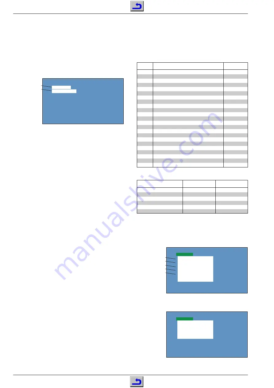
5. Selfcheck
–Activate the service mode (see Point 1.1).
–Press the
9
button.
The selfcheck settings appear on the picture screen.
SELFCHECK
2300xxxx
TIME
: 123456
POWER
: 00
BUS CONT :
OK
BLOCK
:
UV
V1 V2 V3
QV01
Software version
Operating hours
Overload-protection
Bus check
Input source
–Press the
9
button again.
The EPG/TEXT settings appear on the picture screen.
SELFCHECK
EPG/TEXT
QF01 xxx QF10 xxx
QF02 xxx QF03 xxx
QF04 xxx QF05 xxx
Alignment
1. Service Mode
1.1 Activating the service mode
–Press the
p
button.
–Press the
p
button again and keep it pressed while pressing the
MENU
button on the set.
–On the picture screen appear the alignment name and the alignment
value.
RCUT 0410H
40H 10000000B
Alignment Name
Alignment Value
1.2 Ending the service mode
–Press the standby button
A
or switch the set off.
1.3 Button functions
– Remote control buttons
1
R cutoff alignment
Indication: "RCUT"
2
G cutoff alignment
Indication: "GCUT"
3
B cutoff alignment
Indication: "BCUT"
4
Basic contrast
Indication: "SCNT"
5
Basic colour contrast
Indication: "COLP" with PAL
Indication: "COLS" with SECAM
Indication: "COLC" with NTSC
6
NTSC colour adjustment Indication: "TNTC"
9
Selfcheck (see point 5)
e
Test patterns PAL/NTSC (red / green/ blue/ raster/ white, see
Point 3).
ɾ
(yell.)
Convergence alignment (see Point 6).
C A L L
Initialisiation (see Point 2) / clear counter for service hours and
overload protection circuit (see point 5).
Info
Switch off pattern for SCREEN alignment.
– Direct control buttons (on the set)
zɦ
Select service function.
Ł ĵ
Change setting.
MENU
Display/exit alignment menu.
2. Initialization of the QA02
Attention: With this service function, all customer- and service-
specific software settings are cleared.
If the settings of the service functions should be displayable in the case
of service (see Point 4), it is recommended to note down these settings
in order to recover them after the replacement or the initialization of the
QA02.
The QA02 is to be initialized after replacement.
–Activate the service mode (see Point 1.1)
–Press the
CALL
button on the remote control, hold it down and press
the
ɦ
button on the set.
The screen turns black and the set switches temporarily to standby.
–Activate the service mode (see Point 1.1)
–Press the
CALL
button on the remote control, hold it down and press
the MENU button on the set.
Attention:
In this mode, carry out only the following settings,
otherwise the correct function of the set is not guaranteed.
–Use the
z
button to select the "OPT1" service function then use the
Ł ĵ
buttons to set the "7EH" value.
–Use the
z
button to select the "OPT0" service function then use the
Ł ĵ
buttons to set the "B0H" value.
–Check and correct the picture settings (see Points 6 and 7, alignment
no. 1, 3…6).