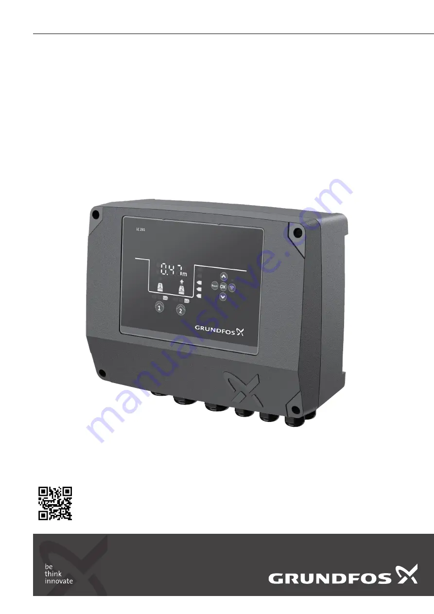
LC 231
Dual pump unit
Installation and operating instructions
LC 231 dual pump unit
Other languageshttp://net.grundfos.com/qr/i/99480674
GRUNDFOS
INSTRUCTIONS
Страница 1: ...LC 231 Dual pump unit Installation and operating instructions LC 231 dual pump unit Installation and operating instructions Other languages http net grundfos com qr i 99480674 GRUNDFOS INSTRUCTIONS...
Страница 2: ......
Страница 3: ...Magyar HU Telep t si s zemeltet si utas t s 243 Italiano IT Istruzioni di installazione e funzionamento 264 Lietuvi kai LT rengimo ir naudojimo instrukcija 286 Latvie u LV Uzst d anas un ekspluat cija...
Страница 4: ...499 CN 522 AR 541 4 LC 231 Table of contents...
Страница 5: ...e product 20 8 1 Overview of alarm and warning codes 20 8 2 Code 2 Power phase missing 20 8 3 Code 4 Too many motor restarts 21 8 4 Code 9 Power phase sequence wrong 21 8 5 Code 12 Service needed 21 8...
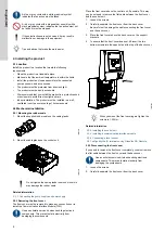
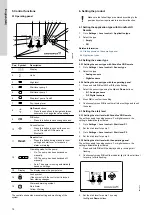
Страница 6: ...Connecting the pump supply and power supply 2 2 2 Removing the front cover The front cover must be removed to make any connections or to install the Communication Interface Module CIM Use an antistati...
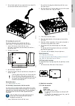
Страница 7: ...nnections Use an antistatic service kit when handling electronic components This prevents static electricity from damaging the components 1 Loosen the screws and remove the front cover Be careful not...
Страница 8: ...s Do not add additional components other than those illustrated on the wiring diagram Do not use unused pin holes for other connections All cable glands and plugs must be mounted after the installatio...
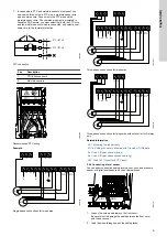
Страница 9: ...L2 L3 L1 PE N N N L2 L3 L1 N B A B A PE PE PE PTC1 PTC2 T2 T3 T1 T2 T3 T1 M1 M2 TM070126 Three phase connections for two pumps L2 L3 L1 PE N N L2 L3 L1 B A B A PE PE PE PTC1 PTC2 T2 T3 T1 T2 T3 T1 M1...
Страница 10: ...vel 1 Loosen the screws and remove the front cover Be careful not to damage the cable between the front cover and the back cover 2 Lead the wires through one of the cable glands 3 Depending on the typ...
Страница 11: ...ter level 8 25 Code 205 Level switch inconsistency 3 7 Testing the product When you have made all the electrical installations and completed the startup wizard you can test the system For emptying app...
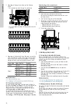
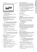
Страница 12: ...ill 1 2 3 4 5 TM0713351 Designation Description 1 High level 2 Stop level 3 Start level P1 start level for pump 1 4 Start level P2 start level for pump 2 5 Dry running level In the filling application...
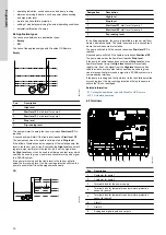
Страница 13: ...t 5 Version number and material number 6 Production code year and week 7 Serial number 8 IC only for UL variants 9 FCC text only for UL variants 10 FCC ID only for UL variants 11 Factory code 12 IP cl...
Страница 14: ...ements to avoid malfunction 6 1 Setting the application type with Grundfos GO Remote 1 Go to Settings Level control Application type 2 Select the type Empty Fill Related information 3 3 Startup wizard...
Страница 15: ...artly empty the pit The after run delay should be set so that the pump stops at the normal stop level to avoid dry running In case of an error the product reports error 165 Signal fault or error 205 L...
Страница 16: ...empts within a set interval 1 Go to Settings Max number of restarts 2 Enable the function 3 Set the interval within which the allowed number of restarts are to be counted 4 Set the maximum number of p...
Страница 17: ...to its normal stage when the temperature has dropped to its trigger level If there is moisture in the pump then the moisture sensor will keep the series connection open until the pump is opened and se...
Страница 18: ...te the warning Contactor wear out appears When 100 of the estimated wear out for the contactor is reached the alarm code 220 Contactor wear out appears on the operating panel and the controller will n...
Страница 19: ...onics Network Intercommunications bus is a fieldbus developed by Grundfos to meet the need for data transfer in all typical Grundfos motor or pump applications Grundfos devices with GENIbus can be wir...
Страница 20: ...itch off the power supply before you start any work on the product Make sure that the power supply cannot be switched on accidentally Fault finding and fault correction must be carried out by qualifie...
Страница 21: ...Wrong configuration Alarm code 25 is shown on the display The alarm symbol on the display turns red and the pump stops Alarm code Wrong configuration is displayed in Grundfos GO Remote Cause The leve...
Страница 22: ...shown on the display The alarm symbol on the display turns red and the pump stops Alarm code Drive unit communication fault is displayed in Grundfos GO Remote Cause Internal communication fault Remedy...
Страница 23: ...e Change the sensor if needed Related information 6 6 1 Setting the after run delay high level 8 23 Code 181 Signal fault PTC input Alarm code 181 is shown on the display The alarm symbol on the displ...
Страница 24: ...1 7 6 DOL PI 7 6 A2 and 40 C 104 F 1 When the maximum number of running pumps is set to 1 it is possible to set the nominal pump current to 12 A 2 When the maximum number of running pumps is set to 1...
Страница 25: ...2 3 2 Protection of controller and supply cables 7 2 Replacing the battery 10 Disposing of the product This product or parts of it must be disposed of in an environmentally sound way 1 Use the public...
Страница 26: ...ps Korea Ltd 6th Floor Aju Building 679 5 Yeoksam dong Kangnam ku 135 916 Seoul Korea Tel 82 2 5317 600 Fax 82 2 5633 725 Latvia SIA GRUNDFOS Pumps Latvia Deglava biznesa centrs Augusta Deglava iel 60...
Страница 27: ...demarks displayed in this material including but not limited to Grundfos the Grundfos logo and be think innovate are registered trademarks owned by The Grundfos Group All rights reserved 2020 Grundfos...