


English (GB)
29
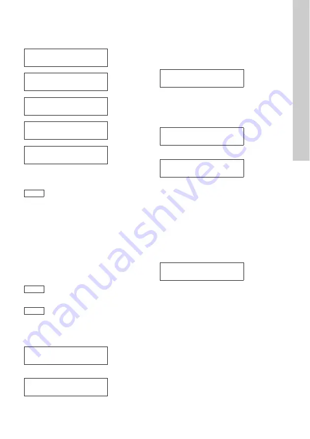
13.2.2 Checking the relays
The first item appears in the "Test functions" menu
and does not need to be selected.
Press [OK] to change to the following items.
The relays for sensor 2 can even be tested if the
device is set to "1 sensor".
1. For
each item, press the [Up] button to switch the
corresponding relay on.
– When switched on, the relay and the
connected warning and protection device will
be activated.
– If this does not happen, check the connected
warning and protection device as well as the
cabling.
2. Press the [Up] button again to switch the
corresponding relay off.
13.2.3 Checking the current outputs
Checking the current outputs for measured value
1
1. Press [OK] to change to the items.
If the device is set to 0-20 mA.
If the device is set to 4-20 mA.
– Now the displayed current (10 mA or 12 mA)
should be present at the current output for
measured value 1.
2. Check this with a suitable measuring device.
3. Press the [Up] button to change to the next
current output.
– Now 20 mA should be present at the current
output for measured value 1.
4. Check this with a suitable measuring device.
5. Press the [Up] button to change to the next
current output.
If the device is set to 0-20 mA.
If the device is set to 4-20 mA.
– Now the displayed cur-rent (0 mA or 4 mA)
should be present at the current output for
measured value 1.
6. Check this with a suitable measuring device.
Checking the current outputs for measured value
2
1. Press [OK] to change to the following items and
check as described above.
13.2.4 Software version
1. Press [OK] to change to the item.
– Now the software version is displayed.
14. Disposal
This product or parts of it must be disposed of in an
environmentally sound way. Use appropriate waste
collection services. If this is not possible, contact the
nearest Grundfos company or service workshop.
M1 - limit 1
OFF
M1 - limit 2
OFF
M2 - limit 1
OFF
M2 - limit 2
OFF
Alarm relay
OFF
Caution
When switching on a relay, the connected
warning and protection device will also be
activated!
Note
If the displayed values cannot be
measured, the current output is defective.
Note
The current output for measured value 2
can even be checked if the device is set to
"1 sensor".
M1 - mA signal
10 mA
M1 - mA signal
12 mA
M1 - mA signal
20 mA
M1 - mA signal
0 mA
M1 - mA signal
4 mA
*Service info*
Vx.xx
dd.mm.yyyy
Содержание Conex DIS-G
Страница 1: ...Conex DIS G Gas warning controller Installation and operating instructions GRUNDFOS INSTRUCTIONS ...
Страница 2: ...2 ...
Страница 345: ...345 ...


