English (GB)
19
10.3 Relay outputs
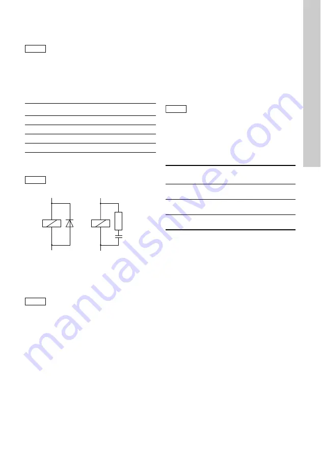
With inductive loads (including
relays and
contactors), interference suppression is necessary. If
this is not possible, protect the relay contacts using a
suppressor circuit as described below.
•
With AC voltage:
•
With DC voltage: Connect the free-wheeling
diode in parallel to the relay or contactor.
Fig. 7
Suppressor circuit DC / AC
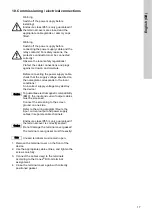
10.4 Current output
Connection via 2-wire cable with single screen.
Maximum length: 1000 metres.
The current output can be set to one of the two
standard ranges "0-20 mA" or "4-20 mA".
Output 1: sensor 1
This current output emits
the displayed measured
value as an analog current signal.
Use of current signal for measured values:
•
As input signal for another indicator.
1. Connect the + conductor to terminal 20.
2. Connect the - conductor to terminal 21.
3. Connect the screen to the protective earth
conductor (PE).
Output 2: sensor 2
This current output emits
the displayed measured
value as an analog current signal.
Use of current signal for measured values:
•
As input signal for another indicator
1. Connect the + conductor to terminal 23.
2. Connect the - conductor to terminal 24.
3. Connect screen to the protective earth conductor
(PE).
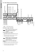
10.5 Connection of sensors
10.5.1 Amperometric sensors
Connection via 2-wire cable 0.5 mm
2
with single
screen. Maximum length (maximum distance
between the sensor disc and gas warning controller):
100 metres.
Cables for amperometric gas sensors
The wire colours refer to Grundfos cable.
Sensor 1:
•
Connect the brown wire (+) to terminal 26.
•
Connect the white wire (-) to terminal 27.
•
Connect the screen to PE.
Sensor 2:
•
Connect the brown wire (+) to terminal 30.
•
Connect the white wire (-) to terminal 29.
•
Connect the screen to PE.
Note
The connection of the relay outputs
depends on the application and the final
control elements used. Therefore the
connections described below should only
be considered as guidelines.
Current up to
Capacitor C
Resistor R
60 mA
10 nF, 275 V
390
Ω
, 2 W
70 mA
47 nF, 275 V
22
Ω
, 2 W
150 mA
100 nF, 275 V
47
Ω
, 2 W
1.0 A
220 nF, 275 V
47
Ω
, 2 W
Caution
Provide the relay outputs with a
corresponding backup fuse!
TM
03
7
209
2
813
Caution
Ensure correct polarity!
Maximum load: 400
Ω
+
-
DC
R
C
AC
Caution
Connect the screening to screen ground
on one side only!
Description
Product
number
Connection cable for amperometric
gas sensors, 10 metres
96725670
(321-130/10)
Connection cable for amperometric
gas sensors, 20 metres
96725672
(321-130/20)
Connection cable for amperometric
gas sensors, 50 metres
96725673
(321-130/50)
Содержание Conex DIS-G
Страница 1: ...Conex DIS G Gas warning controller Installation and operating instructions GRUNDFOS INSTRUCTIONS ...
Страница 2: ...2 ...
Страница 345: ...345 ...


