Modbus for MP 204
CIU 200 Modbus RTU CIU 250 GSM/GPRS CIU 500 Ethernet for Modbus TCP
Functional profile and user manual
GRUNDFOS
INSTRUCTIONS
Страница 1: ...Modbus for MP 204 CIU 200 Modbus RTU CIU 250 GSM GPRS CIU 500 Ethernet for Modbus TCP Functional profile and user manual GRUNDFOS INSTRUCTIONS...
Страница 2: ...5 MP 204 control register block 18 9 6 MP 204 status register block 19 9 7 Alarm code module register 00204 21 9 8 Warning bits registers 00205 and 00206 22 9 9 MP 204 data register block 23 9 10 Ala...
Страница 3: ...e for controlling Grundfos products via infrared or radio Based on smart phone technology GSM Global System for Mobile communications H Head pressure HTTP HyperText transfer protocol The protocol comm...
Страница 4: ...tion via the CIU 250 can be established by using one of the following options Modbus RTU protocol via a GSM connection Modbus TCP protocol via a GPRS connection SMS commands from a mobile phone Fig 2...
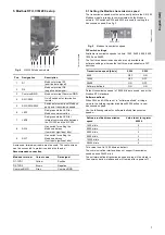
Страница 5: ...n 5 Modbus RTU CIM 200 setup Modbus connection type RS 485 2 wire common Conductors D0 D1 and Common See section 5 Modbus RTU CIM 200 setup Maximum cable length 1200 m Equals 4000 ft Slave address 1 2...
Страница 6: ...ftwareDefinedModbusAddress GSM GPRS visual diagnostics LED1 See section 6 2 Status LEDs Maximum Modbus telegram size 260 bytes Total Modbus TCP IP application data unit See fig 20 Modbus TCP specifica...
Страница 7: ...1200 bits s as default The communication interface does not support transmission speeds above 38400 bits s The software defined transmission speed value will be stored in the communication interface a...
Страница 8: ...he CIM 200 Modbus module and has a value of 150 The CIM 200 has a DIP switch with two switches SW1 and SW2 for cutting the termination resistor in and out Figure 8 shows the DIP switches in cut out st...
Страница 9: ...on active Flashing red Fault in the Modbus communication Permanently red Fault in the CIM 200 Modbus configuration Status Description Off The CIM 200 has been switched off Flashing red No internal com...
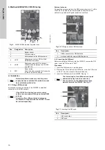
Страница 10: ...Pos Designation Description 1 Battery socket 2 SIM card holder 3 SMA connection for GSM antenna 4 LED1 Yellow green status LED for GSM GPRS communication 5 LED2 Red green status LED for internal commu...
Страница 11: ...parameters see CIM 250 SMS commands supplement to the installation and operating instructions on the CD ROM supplied with the GSM module 6 2 Status LEDs The CIM 250 GSM module has two LEDs See fig 9...
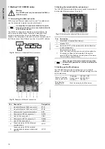
Страница 12: ...arth through earth clamp or to connect cable shield to earth in the connector TM05 6435 4711 TM05 7431 1013 Pos Description Designation 1 Industrial Ethernet RJ45 connector 1 ETH1 2 Industrial Etherne...
Страница 13: ...connected User admin default Password Grundfos default Note User and password may have been changed fromtheir factory default values TM05 6436 4712 Note Both ETH1 and ETH2 can be used to establish a c...
Страница 14: ...egisters meaning that either function 0x03 or 0x04 can be used for reading data Type Code Hex Name 16 bit data registers 03 0x03 Read holding registers 04 0x04 Read input registers 06 0x06 Write singl...
Страница 15: ...riting values Each register block will be specified in more detail in the following sections Start address Register block Permissions Description 00001 CIM configuration R W Configuration of the CIM m...
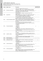
Страница 16: ...ined transmission speed enumeration The software defined transmission speed value is stored in the device and will remain after a power off 0 1200 bits s 1 2400 bits s 2 4800 bits s 3 9600 bits s 4 19...
Страница 17: ...ed with the GSM module GeneralStatus Bit 1 WriteAccess Remote write access 0 No write access the PIN code is incorrect 1 Full write access the PIN code is either correct or not enabled 00030 UnitFamil...
Страница 18: ...hat resets the NumberOfStartsTripCounterHI LO registers 00342 and 00343 0 No resetting 1 Resetting This control bit is triggered on rising edge only i e setting logical 0 to 1 See section 9 2 CIM conf...
Страница 19: ...sing the T button The alarm code 18 is shown in the display The behaviour is equal to MotorProtectionTrip 2 Actuator stop off result of control register 00101 bit 2 This mode is the result of the stat...
Страница 20: ...2 CIM configuration register block address 00005 AcknowledgeRegister Bit 7 ResetLogsAck Indicates if a ResetLogs control bit was acknowledged by the device 0 No acknowledgement 1 Control bit acknowle...
Страница 21: ...lay Value 56 Underload current too low A W Delay Value 64 Overtemperature Tempcon measurement A W Condition delay E D value 71 Overtemperature Pt100 measurement A W Condition delay E D value 91 Signal...
Страница 22: ...e 2 Overload current too high 48 Value 3 Underload current too low 56 Value 4 Current asymmetry 111 Value 5 7 8 Insulation resistance low 20 E D value 9 Overtemperature Tempcon measurement 64 E D valu...
Страница 23: ...315 MotorTemp2 0 01 K Motor temperature measured by PT resistor Motor temperature measured by PT resistor 00316 LineCurrentAsym 0 1 Line current asymmetry 00317 CapacitorStart 1 F Start capacitor valu...
Страница 24: ...lue of line current Logged maximum value of line current 00351 CurrentLineMinLog 0 1 A Logged minimum value of line current Logged minimum value of line current 00352 StartsHourMaxLog Unscaled Logged...
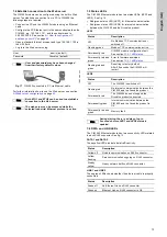
Страница 25: ...the Grundfos product 6 Observe that LED2 turns steady green see section 6 2 Status LEDs indicating that the GENIbus connection is working 7 Observe that LED1 blinks yellow and changes to yellow pulsin...
Страница 26: ...the CIM 500 Web server Factory default address 192 168 1 100 9 Log in to the Web server Default User admin Password Grundfos 10 In the menu column to the left select Configuration Real time Ethernet...
Страница 27: ...have to be made via SMS commands Setting a SCADA PIN code SETSCADACODE access code will enable write access protection Default is an empty SCADA PIN code meaning no protection Activating the SCADA PIN...
Страница 28: ...ed by some service providers Default value is Normal Select Connection type CONNECTION SERVER CLIENT DISABLE Default value is Server Set GPRS roaming GPRSROAMING ON OFF Default value is Off Select Mod...
Страница 29: ...PRS system to ensure that it is still working An automatic procedure ensures restarting of the CIU 250 and repetition of the GPRS connection sequence in case a deadlock situation has occurred It also...
Страница 30: ...e request telegram specifies the starting address the address of the first register to be read and the number of holding registers to read In the telegram register addresses start from zero meaning th...
Страница 31: ...Value Address 0x01 Function code 0x10 Start address HI 0x00 Start address LO 0x00 Quantity HI 0x00 Quantity LO 0x02 Byte count 0x04 Register 33 HI 0x00 Register 33 LO 0x01 Register34 HI 0xB0 Register...
Страница 32: ...CD Field Value Address 0x01 Function code 0x08 Subcode 0x00 Data 0xAB Data 0xCD Bit Description 0 Internal communication failure with the Grundfos CIU 250 1 EEPROM self test failed the test is carried...
Страница 33: ...If there is no response from the slave see section 13 Fault finding Field Value Description Slave address 0x01 Function code 0x06 Write single register Start address HI 0x00 ControlRegister address 0...
Страница 34: ...200 does not support the MP 204 which is connected Contact the nearest Grundfos company 4 The Modbus LED LED1 is constantly red a Fault in the CIM 200 Modbus configuration Check the transmission spee...
Страница 35: ...s will be valid 3 The slave responds with exception response 0x02 Invalid data address a The master is trying to read or write an invalid data address If a master tries to read register addresses that...
Страница 36: ...204 connected Contact the nearest Grundfos company 4 The LED for GSM GPRS communication LED1 is flashing yellow See signal 1 in fig 13 on page 11 a The SIM card has not been inserted Insert the SIM c...
Страница 37: ...nvalid data address If a master tries to read register addresses that are not listed in the tables the slave will respond with this exception response Some masters may automatically try to read large...
Страница 38: ...Check that the individual conductors have been fitted correctly e g not reversed Check the power supply to the Grundfos product 3 The LED for internal communication LED2 is permanently red a The CIM 5...
Страница 39: ...ich will cause problems if some of the registers in the block are not supported An example would be reading the CIM configuration and CIM status blocks in one telegram this is not possible since there...
Страница 40: ...21 1 5 71 4 7 121 7 9 171 A B 221 D D 22 1 6 72 4 8 122 7 A 172 A C 222 D E 23 1 7 73 4 9 123 7 B 173 A D 223 D F 24 1 8 74 4 A 124 7 C 174 A E 224 E 0 25 1 9 75 4 B 125 7 D 175 B F 225 E 1 26 1 A 76...
Страница 41: ...ce 202 External sensor input low 18 Commanded alarm standby trip 99 Signal fault input for analog setpoint 203 Alarm on all pumps 19 Diaphragm break dosing pump 104 Software shutdown 204 Inconsistency...
Страница 42: ...lt water in oil WIO sensor 241 Motor phase failure 65 Motor temperature 1 t_m or t_mo or t_mo1 171 Signal fault moisture sensor 242 Automatic motor model recognition failed 66 Temperature control elec...
Страница 43: ...n tab 7 Configure an IP address and subnet mask to be used by your PC See fig 1 Fig 1 Example from Windows 7 A 2 Web server configuration The built in web server is an easy and effective way to monito...
Страница 44: ...e default value is 502 the official IANA assigned Modbus TCP port number Number 502 will always be active implicitly If you select another value in the web server configuration field both the new valu...
Страница 45: ...Telefax 81 35 448 9619 Korea GRUNDFOS Pumps Korea Ltd 6th Floor Aju Building 679 5 Yeoksam dong Kangnam ku 135 916 Seoul Korea Phone 82 2 5317 600 Telefax 82 2 5633 725 Latvia SIA GRUNDFOS Pumps Latv...
Страница 46: ...6539 The name Grundfos the Grundfos logo and be think innovate are registered trademarks owned by Grundfos Holding A S or Grundfos A S Denmark All rights reserved worldwide Copyright Grundfos Holding...