Installation Manual of SPH series
Страница 1: ...Installation Manual of SPH series...
Страница 2: ...uctions 19 5 4 SPH System Connection Mode 23 6 Commissioning 42 6 1 Commissioning of SPH 42 6 2 Operation modes 42 6 3 Country setting 44 6 4 Display and button 45 6 5 Communication 52 7 Start up and...
Страница 3: ...13 Certificate 65 14 Contact 66...
Страница 4: ...thium battery model it will be dangerous Installer can install energy storage machine of SPH TL BL UP Series rapidly and troubleshooting build communication system through read this manual carefully I...
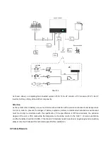
Страница 5: ...not require line of sight between the devices and it is selective purchasing 1 4 Product Description SPH Series is used to store energy generated by the photovoltaic cell panels or energy from grid i...
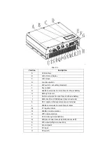
Страница 6: ...ery terminal I CAN communication interface of Lithium battery J RJ45 interface of DRMs used only in Australia K NTC Lead acid temperature sensor terminal L RS485 communication interface of meter M CT...
Страница 7: ...se professional electrical or mechanical engineer 4 During installation please don t touch the other parts within the box 5 All the electrical installation must comply with the local electrical safety...
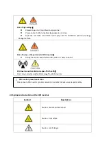
Страница 8: ...to prevent the danger of battery explosion battery recommended installation environment must be strictly in accordance with the specification if the specification is IP20 environment the pollution de...
Страница 9: ...hell of SPH inverter During the work Cover shell around radiator is likely to be hot SPH inverter exists radiation maybe affect health Don t stay a long time within 20cm range from SPH inverter 2 3 Sy...
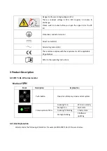
Страница 10: ...ments of the applicable CE guidelines Refer to the operating instructions 3 Product Description 3 1 SPH TL BL UP series inverter Marks of SPH 3 2 Label Explanation Label contains the following informa...
Страница 11: ...Description of label Hybrid Inverter Model name SPH 6000TL BL UP PV input data Max PV voltage 550V d c V PV voltage range 120 550 d c V PV Isc 16 9 d c A 2 Max input current 13 5d c A 2...
Страница 12: ...arent power 4000VA Nominal voltage 230 a c V Rated output current 17 5 a c A Nominal Frequency 50 Hz Power factor range 0 8leading 0 8lagging Battery data Battery voltage range 42 59 d c V Rated charg...
Страница 13: ...Hybrid Inverter Model name GrowattSPH6000 PV input data Max PV voltage 550V d c V...
Страница 14: ...r factor range 0 8leading 0 8lagging EPS output data Rated output apparent power 3000VA Nominal voltage 230 a c V Rated output current 13 5 a c A Nominal Frequency 50 Hz Power factor range 0 8leading...
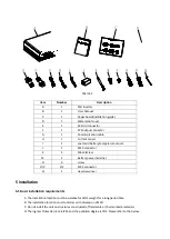
Страница 15: ...ign Can improve self consumption back up and also Pinch the valley Smart management work mode can be set Safe battery used Easy installation Two mpp tracker input 4 Unpacking Please check whether exte...
Страница 16: ...6 setscrew M 2 Battery power terminal N 6 screw O P 2 2 MC4 connector Q 1 Hex screwdriver 5 Installation 5 1 Basic installation requirements A The installation location must be suitable for SPH s weig...
Страница 17: ...e ambient temperature should be 25 60 G SPH can be installed in vertical or lean back on plane please refer to the below Chart 5 2 H Installation position shall not prevent access to the disconnection...
Страница 18: ...rence user manual N The inflammable and explosive dangerous goods must not be placed around battery in case of cause serious danger 5 2 Installation requires tools and RJ 45 terminal sequence of the L...
Страница 19: ...ite green Blue White blue Green White brown Brown 5 3 Installation Instructions 5 3 1 Attention Layout length of sensors consider There re three types of sensors for use with SPH One is wired current...
Страница 20: ...sider the length between SPH with combiner box for the sensor should be installed in the live line And if you installed SP CT for sensor distance recommended not more than 30 meters The installation l...
Страница 21: ...ickness of wall for SPH must be not less than 60mm 2 Make sure the drill position use paper board installation guide put the paper board cling to the wall make sure the top edge of paper board is leve...
Страница 22: ...than 55mm 5 Knock four explosion bolt into 8 holes As the chart 5 8b below 6 Hang the energy storage machine on the four setscrews As the chart 5 8c below 7 Lock the nut of setscrew As the chart 5 8d...
Страница 23: ...o life due to lethal voltages PV array supplies d c voltage to inverter when exposed to light before connecting the PV array Conver some light screens above PV arrays ensure that the DC switch and AC...
Страница 24: ...le of connection cable to negative pole of PV input connector please pay attention to PV input voltage and current within permission Limit Max PV voltage 550V consider the lowest temperature Max PV in...
Страница 25: ...le length Growatt SPH3000 SPH 3000TL UP Growatt SPH3600 S PH 3600 TL UP Growatt SPH4000 S PH 4000 TL UP Growatt SPH4600 S PH 4600 TL UP Growatt SPH5000 S PH 5000 TL UP Growatt SPH6000 S PH 6000 TL UP...
Страница 26: ...2 Thread cables through pressure screw seal ring threaded sleeve in sequence insert cables into connection terminal according to polarities indicates on it and tighten the screws Chart 5 13 Step 3 Pus...
Страница 27: ...tation to tighten the socket counterclockwise rotation to loosen the socket Recommended wiring diagram in Australia is as follows Chart 5 15 SPH3000 6000TL BL UP Note This diagram is an example for gi...
Страница 28: ...gram is an example for Australian and New Zealand gird system where neutral line can t be switched Chart 5 17 Growatt SPH3000 6000 Note This diagram is an example for customer who only wants to use th...
Страница 29: ...7 The first start of system needs Grid power 5 4 3 Connection of battery terminal Install battery cable steps are as follows 1 Unscrew the swivel nut from the cable gland 2 Thread the swivel nut over...
Страница 30: ...he CT terminal connection steps are as follows 1 Unscrew the swivel nut from the cable gland 2 Thread the swivel nut over the CT cable 3 Press the cable support sleeve out of the cable gland 4 Remove...
Страница 31: ...lock the waterproof cover to the inverter with screws 9 Screw the swivel nut onto the waterproof cover Chart 5 21 Chart 5 22 Chart 5 23 Note 1 The meter and CT can t be installed at same time please...
Страница 32: ...Chart 5 24 During the actual operation please pay attention to the installation of current transformer as the diagram shows below Chart 5 25 As illustrated above open the current transformer and you c...
Страница 33: ...of the cable gland 4 Remove the filler plug from the cable support sleeve 5 Route the LAN cable through an opening in the cable support sleeve 6 Thread the LAN cable through the cable gland 7 Insert t...
Страница 34: ...le PYLON US2000B connect lithium battery terminal RJ45 steps as follows 1 Unscrew the swivel nut from the cable gland 2 Thread the swivel nut over the CAN cable 3 Press the cable support sleeve out of...
Страница 35: ...batteries which need to connect BMS system of the battery connect lithium battery terminal RJ45 steps as follows 1 Unscrew the swivel nut from the cable gland 2 Thread the swivel nut over the RS485 ca...
Страница 36: ...sed please do not remove the filler plug from the cable support sleeve 5 4 8 Connection of DRMS terminal Australia only When SPH is applied to Australia the DRMS terminals need to be connected the con...
Страница 37: ...ed to be installed lock the waterproof cover to the inverter with screws 9 Screw the swivel nut onto the waterproof cover Chart 5 32 Chart 5 33 RJ45 terminal pin assignment PIN assignment for inverter...
Страница 38: ...lead acid battery the temperature probe of the lead acid battery is used to detect the ambient temperature of the lead acid battery the battery temperature cable of the SPH side connection steps are...
Страница 39: ...is used to communicate with external devices such as remote start hot water heater The wiring steps are as follows 1 Unscrew the swivel nut from the cable gland 2 Thread the swivel nut over the cable...
Страница 40: ...y contact cable is not used please do not remove the filler plug from the cable support sleeve 5 4 11 Grounding connection SPH must be grounded by cable the grounding point is showed as follow and the...
Страница 41: ...e minimum wire diameter is 10 0mm2 DC Grounding Select the DC Grounding mode according to the local standard and use the PV grounding terminal box and DC Grounding wires of the same specification Grou...
Страница 42: ...can set up to three periods of the priority mode refer to 6 3 4 1 Load first Load first is the default mode when it s working in this mode PV energy would offer to load and battery prior when PV is I...
Страница 43: ...ail s fault information please refer to 9 1 2 Some fault information is in order to remind users that might have some faults occurred in inverter side 6 2 3 Programming mode Programming mode indicates...
Страница 44: ...to the next item Press enter key more than 1 seconds to make sure Default Set WorkMode Auto Test WorkMode ExportLimit WorkMode Chart 6 1 Caution When you setting the DIP you must turn off PV switch AC...
Страница 45: ...to ON its value turns to 1 when set downward its value turns to 0 Concerning the matching of the PIN status and the country safety standard please refer to the table below 6 4 Display and button 6 4...
Страница 46: ...ton D Enter button E UP button Notice LED showing status of SPH it has two colors one is green and another is red Please turn to 3 1 and read the detail of LED 6 4 3 LCD display column Grovett can pro...
Страница 47: ...in self check state if there is no error or warning SPH will go to normal state or standby state Otherwise it will go to fault state 4 Programming state SPH is in updating firmware state 5 Fault stat...
Страница 48: ...situation If SPH is normal state it will show normal If SPH is standby state it will show as standby etc 3 Some special definitions are explained for example Vb means the voltage of battery Cb means...
Страница 49: ...rkMode Priority WorkMode BackUp Press enter key more than 3 seconds into setup mode Press down key to the next item Press enter key more than 1 seconds to make sure Default Set WorkMode Auto Test Work...
Страница 50: ...ic Parameter Only display when battery type is lead acid Only display when battery type is lead acid Only display when battery type is lead acid Chart 6 7 In the basic Parameter you can set language E...
Страница 51: ...after pressing Enter MODE Change WorkMode Sensor WorkMode Cable CT WorkMode Meter SP CT Battery Type WorkMode Lithium WorkMode Lead acid Press enter key to make sure Press down key to the next item Pr...
Страница 52: ...nection Point will drop to the Agreed Export Capacity or less within the specified time Note 1 Default value is 00 0 2 Fail safe works only in meter mode 6 Under the default set you can see the setup...
Страница 53: ...wing communication solution to monitor the SPH Note This kind of monitoring can only be used by the monitor of Growatt s Shineserver shine phone provided by the company Through RS232 interface connect...
Страница 54: ...machine When use battery please pay attention to the follow information Caution Do not dispose of batteries in a fire The batteries may explode Caution Do not open or damage batteries Released electro...
Страница 55: ...e whole system are off 9 Fault removal Our products are carried out with strict tests before they take out if the operation difficulties in the process of installation please log on to www ginverter c...
Страница 56: ...tart can t solve the problem PairingTimeOut Communication fault Check the distance of SP CT and inverter is in the range of specification or not Restart inverter and SP CT reconnect CT LN Reversed LN...
Страница 57: ...eport warning Check the warning information from lithium battery user manual Please contact Growatt service center if restart can t solve the problem BMS error XXX BMS report error Check the warning i...
Страница 58: ...Restart inverter Please contact Growatt service center if restart can t solve the problem Error 408 Temperature over range Please check the temperature is in the range of specification or not PV Volta...
Страница 59: ...roduct Transport damage Breaking of the original manufacturers seal Non observance of Growatt installation and maintenance instruction Failure to observe the applicable safety regulations Power failur...
Страница 60: ...ents must meet the size of the inverter and can support energy storage machine overall weight 11 3 Storing SPH inverter Store SPH inverter in a dry place where ambient temperatures are always between...
Страница 61: ...Backfeed current to the array 0A AC output input data Gowatt SPH SPH TL BL UP Rated input output power 3000 3000 W 3000 300 0W 3000 3680 W 3680 368 0 W 3000 4000W 4000 4000 W 3000 4600 W 4600 460 0 3...
Страница 62: ...400 0VA 3000VA 400 0VA 3000VA 400 0VA 3000VA 4000 VA Nominal voltage 230V 230V 230V 230V 230V 230V Rated Frequency AC output 50 Hz 50 Hz 50 Hz 50 Hz 50 Hz 50 Hz Growatt SPH SPH TL BL UP Rated output...
Страница 63: ...II Others I Ingress protection IP65 Inverter topology Non isolated Operating temperature range 25 C 60 C 13 140 with derating above 45 C 113 Safety level Class I Ingress protection IP65 DC switch Inte...
Страница 64: ...1727 IEC 62116 IEC 62040 C10 11 NRS 097 2 1 Note 1 1 Continuous charging current if there is PV and the PV power is large enough the maximum continuous charging power can reach 4000W If there is no PV...
Страница 65: ...ss meter sensor MR00 0006700 SPM Single phase meter RS485 meter sensor MR00 0008800 TPM three phase meter RS485 meter sensor standard MR00 0008300 RS485 meter sensor for Italy MR00 0008400 13 Certific...
Страница 66: ...rial number 2 SPH inverter module information 3 SPH inverter communication mode 4 SPH inverter fault information code 5 SPH inverter Display content 6 The manufacturer and model of the battery 7 Batte...