background image

10 


©Alcor 2011 All rights reserved 


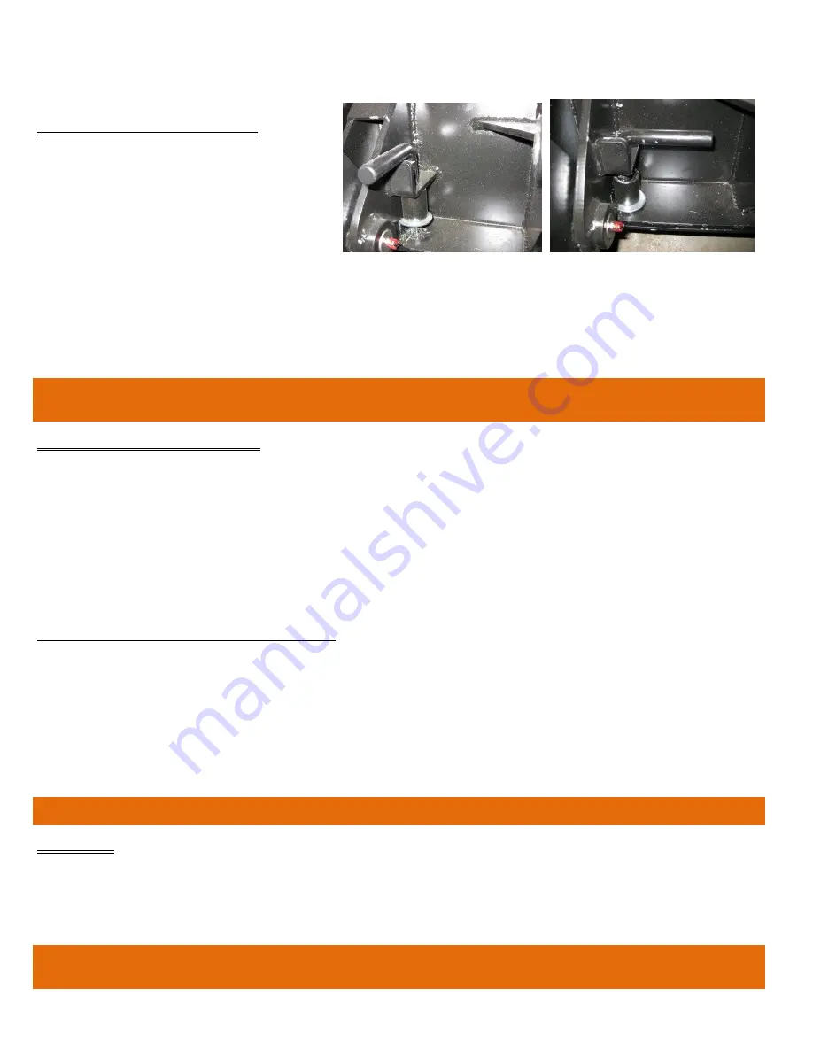
MOUNTING ATTACHMENTS 


Check and clean the attachment plate 
surfaces and place the lock pins in the 
unlocked position. (Fig. 8) 


Check that all controls are in their neutral 
or “OFF” position. (Fig. 3) 


Stand on the operator platform and start 
the engine. 


Drive up to the attachment and line up the attachment plate with the attachment’s mating plate lip. 


Tilt the attachment plate back lifting the attachment off the ground just enough.  Lift the loader arms is necessary. 


Turn the engine off. (Fig. 7) 


Place the lock pins in their locked position and make certain they are inserted all the way threw the pin holes on the 
attachment. (Fig. 9) 

WARNING; 


DO  NOT  OPERATE  THE  MACHINE  WITH  AN  ATTACHMENT  THAT  IS  NOT 
PROPERLY SECURED BY THE LOCK PINS.


RELEASING ATTACHMENTS 


Drive the G41 to the area where the attachment will be released. 


Set the attachment close to the ground in a way that the lock pins can be turned to the unlocked position. (Fig. 8) 


Turn the engine off. (Fig. 7) 


Place the lock pins in their unlocked position. (Fig. 8) 


Start the engine. 


Lower the attachment to the ground and tilt the attachment plate forward to disengage from the attachment’s mating 
plate lip. 


Reverse away from the attachment. 

OPERATING THE STANDARD BUCKET 


Do not lift more than 500 lbs, (including bucket) or machine may become unstable and tip forward.  


When operating with a full bucket, travel forward and reverse with the bucket as close as possible to the ground, turn 
with caution. 


A full bucket will change the way the machine pivots when turning, moving the pivot position from the rear wheels 
to the front wheels. 


Move as close as possible to the dump area and stop before lifting to dump. 


Lift the loader arms slowly to have a feel for the balance of the machine.  Dump the load as soon as possible. 


WARNING: 


NEVER TRAVEL OR TURN WITH A RAISED BUCKET


LOUVERS 


The G41 is equipped with louvers to protect the hydraulic components from falling debris. 


The machine can be used without the louvers on very hot days where prolonged use may generate a lot of heat. 


It is up to the operator to decide if the work being performed allows the machine to be used without these protective 
louvers. 

WARNING: 


ALWAYS USE THE CYLINDER LOCK WHEN REMOVING OR INSTALLING 
THE LOUVERS. 

Unlocked position 

Locked position 

Fig. 8 

Fig. 9 

Содержание G41

Страница 1: ...PENDABLE SERVICE IF OPERATED ACCORDING TO INSTRUCTIONS THE MANUFACTURER PROVIDES THE FOLLOWING INSTRUCTIONS FOR USE AND CARE OF THIS EQUIPMENT AND RELIES UPON THE PURCHASER TO SEE TO IT THAT THESE INS...

Страница 2: ...CONTROLS 7 ATTACHMENT PLATE AND CONNECTORS 8 WORKING AREA 8 OPERATING PRECAUTIONS 8 OPERATING THE G41 9 START UP PROCEDURE 9 SHUT DOWN PROCEDURE 9 MOUNTING ATTACHMENTS 10 RELEASING ATTACHMENTS 10 OPER...

Страница 3: ...fety of all job site personnel it is mandatory that the instructions provided for the use and handling of the equipment be read and thoroughly understood by the operators CAUTION INTENDED USE THIS MAC...

Страница 4: ...FERS INSPECT ROOF DECK Before allowing equipment and personnel access to roof make certain roof is strong enough to support the weight Check load limits of deck with owner builder or architect Clear t...

Страница 5: ...ctors Make certain all pins and bolts are used and secure Always use the cylinder lock if maintenance is required under the loader arms and or you want to keep the loader arms up without being on the...

Страница 6: ...unter clockwise rotation of a hydraulic motor or in and out of a hydraulic cylinder Keep from using the detent if operating an accessory with a cylinder The G41 also provides the ability to decide how...

Страница 7: ...This lever will direct oil flow to the accessory The operator can either push or pull on the lever to send oil flow to a hydraulic cylinder Or if the accessory has a hydraulic motor the lever can be...

Страница 8: ...and or reverse at a reduced speed Do not make sharp turns at speed and try to come to a stop smoothly Stop operating the machine if someone wanders to close Never exceed the rated capacity on the G41...

Страница 9: ...erator s platform put the choke lever to the left or ON position put the throttle lever about half way and turn the ignition key as soon as the engine starts release the key As soon as the engine is w...

Страница 10: ...engine Lower the attachment to the ground and tilt the attachment plate forward to disengage from the attachment s mating plate lip Reverse away from the attachment OPERATING THE STANDARD BUCKET Do no...

Страница 11: ...fuel filter change X Fuel X Spark arrestor muffler X Spark plugs check X Spark plugs change X Battery terminals X Hydraulic oil level X Hydraulic oil change X Hydraulic oil filter change X X Hydrauli...

Страница 12: ...before refuelling never fill the tank completely allow some space for fuel expansion Wipe up any spills before engine is started Fig 12 SPARK ARRESTOR MUFFLER Inspect spark arrestor for carbon build...

Страница 13: ...da to cause cancer and reproductive harm Wash hands after handling Battery Electrolyte First Aid Battery fluid External contact Flush with water Eyes Flush with water for at least 15 minutes and get m...

Страница 14: ...at the level sight glass window oil level should be near the top of the level sight glass window Add oil if necessary Reinstall the louvered covers Remove the cylinder lock and lower the loader arms C...

Страница 15: ...r lift arms Fig 16 Grease the pivot pins on the bottom of the loader lift arms Fig 17 Grease the pivot pins on the lift cylinder Fig 18 and Fig 19 Grease the pivot pins on the tilt cylinder Fig 20 and...

Отзывы: