background image

-46-

Model G0923 (Mfd. Since 05/20)

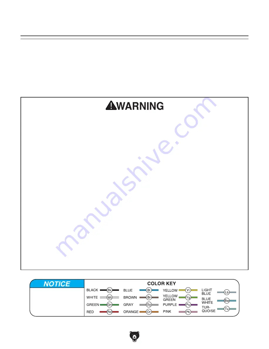
SHOCK HAZARD. Working on wiring that is con-
nected to a power source is extremely dangerous. 
Touching  electrified  parts  will  result  in  personal 
injury  including  but  not  limited  to  severe  burns, 
electrocution,  or  death.  Disconnect  the  power 
from the machine before servicing electrical com-
ponents!

MODIFICATIONS.  Modifying  the  wiring  beyond 
what is shown in the diagram may lead to unpre-
dictable  results,  including  serious  injury  or  fire. 
This includes the installation of unapproved after-
market parts.

WIRE CONNECTIONS.  All  connections  must 
be  tight  to  prevent  wires  from  loosening  during 
machine  operation.  Double-check  all  wires  dis-
connected or connected during any wiring task to 
ensure tight connections.

CIRCUIT REQUIREMENTS.  You  MUST  follow 
the requirements at the beginning of this manual
when connecting your machine to a power source. 

WIRE/COMPONENT DAMAGE. Damaged wires 
or  components  increase  the  risk  of  serious  per-
sonal injury, fire, or machine damage. If you notice 
that any wires or components are damaged while 
performing  a  wiring  task,  replace  those  wires  or 
components.

MOTOR WIRING. The motor wiring shown in
these diagrams is current at the time of printing
but may not match your machine. If you find this
to be the case, use the wiring diagram inside the 
motor junction box.

CAPACITORS/INVERTERS. Some capacitors
and power inverters store an electrical charge for 
up  to  10  minutes  after  being  disconnected  from 
the  power  source.  To  reduce  the  risk  of  being 
shocked, wait at least this long before working on 
capacitors.

EXPERIENCING DIFFICULTIES. If you are expe-
riencing difficulties understanding the information 
included  in  this  section,  contact  our  Technical 
Support at (570) 546-9663.

Wiring Safety Instructions

The photos and diagrams 
included in this section are 
best viewed in color. You 
can view these pages in 
color at www.grizzly.com.

These pages are current at the time of printing. However, in the spirit of improvement, we may make chang-
es to the electrical systems of future machines. Compare the manufacture date of your machine to the one 
stated in this manual, and study this section carefully.

If there are differences between your machine and what is shown in this section, call Technical Support at 
(570) 546-9663 for assistance BEFORE making any changes to the wiring on your machine. An updated 
wiring  diagram  may  be  available. 

Note:  Please gather the serial number and manufacture date of your 

machine before calling. This information can be found on the main machine label.

SECTION 8: WIRING

machine

Содержание G0923

Страница 1: ...L INC WARNING NO PORTION OF THIS MANUAL MAY BE REPRODUCED IN ANY SHAPE OR FORM WITHOUT THE WRITTEN APPROVAL OF GRIZZLY INDUSTRIAL INC AI20901 PRINTED IN CHINA V1 05 20 MODEL G0923 3D PRINTER OWNER S MANUAL For models manufactured since 05 20 ...

Страница 2: ...ng grinding tool integrity and the usage of personal protective equipment The manufacturer will not be held liable for injury or property damage from negligence improper training machine modifications or misuse Some dust created by power sanding sawing grinding drilling and other construction activities contains chemicals known to the State of California to cause cancer birth defects or other repr...

Страница 3: ...reparing 3D Models 19 Navigating Slicer Software 20 Leveling Build Plate 24 Preparing Build Plate 26 Preheating Nozzle 26 Printing 27 Changing Filament 29 Cleaning Build Plate 30 Moving Axes 30 SECTION 5 ACCESSORIES 32 SECTION 6 MAINTENANCE 33 Schedule 33 Cleaning Protecting 33 Lubrication 33 SECTION 7 SERVICE 34 Troubleshooting 34 Cleaning Nozzle 37 Replacing Nozzle 41 Cleaning Feeder Bowden Tube...

Страница 4: ...ade every effort to be exact with the instruc tions specifications drawings and photographs in this manual Sometimes we make mistakes but our policy of continuous improvement also means that sometimes the machine you receive is slightly different than shown in the manual If you find this to be the case and the difference between the manual and machine leaves you confused or unsure about something ...

Страница 5: ...ocations of the controls and features shown below to better understand the instructions in this manual To reduce risk of machine damage and injury read this entire manual BEFORE using machine Feeder Print Head Build Plate Control Knob Display SD Card Slot Filament Spool Spool Holder ...

Страница 6: ...Press control dial to open menu or select menu item Rotate control dial to move through menu options or change input value B SD Card Slot Printer reads G code from SD card to print objects C Display Shows print status and machine menus Refer to Display on next page for more information Figure 2 Feeder components D F Figure 3 Print head G H E D Hobbed Gear Rotates to push filament through feeder to...

Страница 7: ...hows current nozzle temperature Print Speed Percentage Shows print speed as a percentage of value set in G code Status Displays status of printer Cooling Fan Speed Shows speed of cooling fan as a percentage of max speed Axis Locations Shows current locations of each axis Elapsed Time Shows time since print began Print Progress Shows approximate progress of print as a progress bar Status Target Tem...

Страница 8: ...ses axis points and commands Home Position A fixed point on the machine set with proximity switches It is the zero point for X Y and Z axes Hot End The heated portion of the extruder including heat sinks heating block and nozzle Infill The interior material of a 3D printed object Can often be printed at a lower density than the shell Nozzle The component that funnels molten filament out of the pri...

Страница 9: ...trical Power Requirement 120V Single Phase 60 Hz Full Load Current Rating 6A Minimum Circuit Size 15A Connection Type Cord Plug w AC Adapter Power Cord Included Yes Power Cord Length 5 ft w Adapter Power Cord Gauge 18 AWG Plug Included Yes Included Plug Type 5 15 Switch Type Toggle Switch on AC Adapter Motor X Axis Stepper Motor Frame Size NEMA 17 Amps 1 5A Speed 0 600 RPM Type Stepper Brushless P...

Страница 10: ...micron Print Speed 50 100 mm s Number of Extruders 1 Nozzle Diameter 0 4 mm Filament Compatibility PLA Filament Diameter 1 75 mm Print File Type GCODE Software Information Included Software Grizzly Winware Supported OS Windows Supported Object File Types STL OBJ DAE AMF 3MF Construction Build Plate Plastic Rails Steel Other Related Information Connectivity USB SD Card Display 3 2 in LCD Controls R...

Страница 11: ...d proof DANGEROUS ENVIRONMENTS Do not use machinery in areas that are wet cluttered or have poor lighting Operating machinery in these areas greatly increases the risk of accidents and injury MENTAL ALERTNESS REQUIRED Full mental alertness is required for safe operation of machin ery Never operate under the influence of drugs or alcohol when tired or when distracted For Your Own Safety Read Instru...

Страница 12: ...h moving parts or flying debris Make sure they are properly installed undamaged and working correctly BEFORE operating machine FORCING MACHINERY Do not force machine It will do the job safer and better at the rate for which it was designed NEVER STAND ON MACHINE Serious injury may occur if machine is tipped or if the cutting tool is unintentionally contacted STABLE MACHINE Unexpected movement dur ...

Страница 13: ...d build plate can burn immediately on con tact Do not touch nozzle or build plate when hot Allow components time to cool before performing maintenance MAINTENANCE SERVICE Always stop printer and wait for parts to come to a stop before making adjustments or servicing PINCH HAZARD Do not reach into machine or touch built plate during operation Injury may occur if operator comes into contact with mov...

Страница 14: ...rsized circuit To reduce the risk of these hazards avoid over loading the machine during operation and make sure it is connected to a power supply circuit that meets the specified circuit requirements For your own safety and protection of property consult an electrician if you are unsure about wiring practices or electrical codes in your area Note Circuit requirements in this manual apply to a ded...

Страница 15: ...ord size gets longer and the gauge size gets smaller higher gauge numbers indicate smaller sizes Any extension cord used with this machine must be in good condition and contain a ground wire and matching plug receptacle Additionally it must meet the following size requirements Minimum Gauge Size 16 AWG Maximum Length Shorter is Better 50 ft Grounding Plug Requirements Figure 5 Typical 5 15 plug an...

Страница 16: ... replacements can be obtained at your local hardware store NOTICE If you cannot find an item on this list care fully check around inside the machine and packaging materials Often these items get lost in packaging materials while unpack ing or they are pre installed at the factory This machine was carefully packaged for safe transport When unpacking separate all enclosed items from packaging materi...

Страница 17: ...re Part 1 Q Set Screw M4 7 x 4 Spare Parts 2 R Set Screw M3 5 x 3 Spare Parts 2 S Insulated Tubing Spare Part 1 Figure 7 Parts and tools bag O P Q R S N M Figure 8 Minimum working clearances 13 12 Consider anticipated space needed around print er to access printed objects and other machin ery nearby when establishing a location for this machine Below is the minimum amount of space needed for the p...

Страница 18: ... box Assembly includes attaching the spool hanger and connecting the power cord To assemble machine 1 Insert spool hanger into handle see Figure 9 2 Hang spool of PLA filament on spool hanger see Figure 9 3 Connect power adapter to power cord see Figure 10 4 Connect power adapter to machine see Figure 10 Handle Spool Spool Hanger Power Adapter Power Receptacle Power Cable ...

Страница 19: ...chine properly homes Injury or product damage can result from using this machine BEFORE understanding its controls and related safety information DO NOT operate or allow others to operate machine until the information is understood To install slicer software 1 Insert SD card into USB adapter then insert adapter into PC 2 On the SD card navigate to and open EXE installation file 3 Follow directions...

Страница 20: ...azines or websites To complete a typical operation the operator does the following 1 Creates or downloads 3D model 2 Uses slicer software to prepare GCODE file then loads file onto SD card 3 Ensures build plate is clean and level 4 Applies adhesive to build plate 5 Preheats nozzle 6 Loads filament into machine 7 Starts print 8 Removes model from build plate when print is complete If you are not ex...

Страница 21: ...d Of note www thingyverse com is a repository of over a million 3D models available for free download Most of these are shared via a creative commons license allowing users to adapt and redistribute models for non commercial purposes as long as proper credit is given TinkerCAD FreeCAD SketchUP Free and Blender are free to use design software These programs have different strengths and weakness es ...

Страница 22: ... Page 22 Mirror Enters mirror model mode Refer to Manipulating Models on Page 22 Per Model Settings Opens menu for model spe cific settings when printing multiple models at once Build Area Frame Shows build area of selected printer Model Visualization Shows model within build area Right click and drag to rotate view Scroll mouse wheel to zoom Build Area Frame Object Size Shows print object max dim...

Страница 23: ...object viewer 4 Adjust model based on your printing needs Refer to Manipulating Model on Page 22 and Adjusting Print Settings on Page 23 for more detailed information 5 Select the Prepare button see Figure 14 It will take a few seconds to prepare the file Figure 13 Location of open file icon Open File Icon Figure 14 Location of prepare button Prepare 6 Select Save to File see Figure 15 If Save to ...

Страница 24: ...20 The view can be rotated by right clicking the mouse and dragging it or panned by alt clicking the mouse usually the middle mouse button and dragging it Scrolling the mouse wheel zooms the view in and out Movement Handles Axis Fields Scaling Models The Scale icon see Figure 18 opens scale model mode When this mode is active the selected object can be scaled by dragging the X Y and Z handles Alte...

Страница 25: ... can be modified for an expedited print time or to create an object that needs extra durability Enable Gradual This setting automatically deter mines the infill based on the model increasing the infill percentage towards the top and bottom of the print This setting can be used to resolve bubbling that occurs where the top layers of the print do not cool properly and sink into the infill Generate S...

Страница 26: ...D printing from other sourc es you will find that the custom print setup has the options you need to make successful prints Leveling Build Plate Tools Needed Qty Sheet of Paper 1 To level build plate with automatic function 1 Press control dial to open main menu 2 Navigate to Prepare then to Level bed Axes will home and Click to Begin will appear on display 3 Press control dial to begin Nozzle wil...

Страница 27: ...t 1 of 4 Tools Needed Qty Sheet of Paper 1 To level build plate 1 Navigate to Auto Home from main menu Wait for axes to home 2 Move axes so nozzle is over front left corner of build plate For more information refer to Moving Axes on Page 30 3 Slide paper under nozzle see Figure 25 Adjust wing nut under nozzle until nozzle barely touches paper Note There should be noticeable resistance but paper sh...

Страница 28: ...eheating 1 Press control dial to open main menu 2 Navigate to Preheat and press control dial to start process Display will return to status screen and current temperature will begin to change as nozzle heats up Preheating stops when current nozzle temperature matches target temperature see Figure 27 Figure 27 Preheating temperature indicators on status screen Target Temperature Current Nozzle Temp...

Страница 29: ... 2 Insert SD card into SD slot see Figure 28 3 Press control dial to open main menu 4 Use control dial to select Print from SD navigate to prepared file then press control dial Axes will home then printing will begin Note During printing display returns to sta tus screen see Figure 29 Figure 28 SD slot above display SD Card in SD Slot Figure 29 Print status screen Figure 30 Print menu 2 Select Pau...

Страница 30: ...ally see Starting Print on Page 27 Instead of GCODE file choose GRIZZLY G file Printer will resume printing from last position Settings can be changed during printing This includes nozzle temperature print speed and print head position To change print settings 1 During printing press control dial to open print menu see Figure 34 Figure 34 Print menu 2 Select Tune Print settings include Speed Chang...

Страница 31: ...be pinched against hobbed gear see Figure 37 Figure 37 Filament installed in feeder Figure 38 Loading filament status screen 6 Press control dial Feeder will begin to push filament into print head Wait for process to complete see Figure 38 Tensioner To change filament 1 Press control dial to open main menu 2 Select Change filament Nozzle will begin preheating then feeder will begin to retract fila...

Страница 32: ...n build plate to ensure it does not attract debris Accumulation of dust and fila ment residue on the build plate prevents printed layer from adhering evenly Dried glue can be scraped off using a flat edged tool such as a putty knife Alternatively run build plate under warm water until glue softens and rinses off Dry build plate before use Moving Axes Sometimes it is necessary to move the axes to a...

Страница 33: ...g print head and build plate along axis rails Homing All Axes Homing Individual Axes 1 Press control dial to open main menu 2 Select Auto Home X Y and Z axes will move to machine zero as determined by axis limit switches 1 Press control dial to open main menu 2 Select Prepare then select Single axis home Single axis home menu will open see Figure 42 3 Select axis to home Chosen axis will move to m...

Страница 34: ...ories order online at www grizzly com or call 1 800 523 4777 PLA Filament Spools T31834 Clear Filament for 3D Printers T31835 Red Filament for 3D Printers T31836 Blue Filament for 3D Printers T31837 Yellow Filament for 3D Printers T31838 White Filament for 3D Printers T31839 Black Filament for 3D Printers 1 75mm diameter PLA filament for use with Grizzly 3D printers T31840 3D Printer Nozzle for G0...

Страница 35: ...Any other unsafe condition Weekly Maintenance Wipe down dust filament residue Monthly Maintenance Clean nozzle with brush and needle Page 37 Clean feeder Bowden tube Page 43 Schedule Cleaning the Model G0923 is relatively easy Remove excess filament that has build up on the machine and wipe away dust or residue with a dry cloth Wipe dust and residue off Z axis leadscrew and apply light machine oil...

Страница 36: ...e belt s ensure pulleys are aligned Page 44 2 Wire motor correctly Page 46 3 Tighten replace loose drive sprockets 4 Test repair replace 5 Test repair replace Machine has vibration or noisy operation 1 Cooling fan loose or damage 2 Motor loose 3 Motor at fault 1 Test repair replace 2 Tighten motor to chassis 3 Test repair replace Symptom Possible Cause Possible Solution Filament does not extrude d...

Страница 37: ...ripped threads 10 Heating block at fault 1 Adjust temperature and restart preheating process Page 26 Lower temperature may require slower print speed 2 Unwind filament from spool until it is not tangled or overlapping 3 Replace filament Page 29 4 Level build plate Page 24 5 In slicer software select print speed settings appropriate for type of filament 6 Tighten feeder tension Page 4 7 Remove fila...

Страница 38: ...or leadscrew 1 Tension replace belt s ensure pulleys are aligned Page 44 2 Tighten replace loose drive sprockets 3 Clean and lubricate leadscrew Page 33 4 Test repair replace Occasional layer is missing 1 Z axis leadscrew dirty 2 Bent or misaligned axis rods or leadscrew 1 Clean and lubricate leadscrew Page 33 2 Test repair replace Fine detail does not print 1 Print resolution too low 2 Build plat...

Страница 39: ...using a guitar string A clogged nozzle often leads to major printing issues Regularly performing brush and needle cleaning will help keep the Model G0923 printing smoothly for many hours of work Performing a cold pull when changing filaments helps remove old filament from the interior of the nozzle This process uses partially cooled molten filament to pick up and remove burned filament from the in...

Страница 40: ...d in this process Although PLA can get the job done and is easy to acquire it is brittle and breaks easily when pulled out of the print head For a more reliable pull consider using white or clear Nylon filament If filament other than PLA is used adjust preheating temperatures accordingly Figure 48 Removing Bowden tube Figure 49 Cold pull filament ends If removed end has carbonization and residue o...

Страница 41: ...Bowden tube see Figure 50 Figure 50 Removing Bowden tube Figure 52 Removing nozzle from heating block 3 Remove bottom plate of print head cover see Figure 51 4 Remove print head cover from print head see Figure 51 Figure 51 Print head cover components 5 Preheat heating block to printing temperature refer to Preheating Nozzle on Page 26 Before proceeding with the next step wear gloves to protect yo...

Страница 42: ...ermal Barrier Tube Heating Block Heat Sink 10 Remove external debris and filament buildup from heating block and thermal barrier tube If thermal barrier tube has excessive build up it can be unscrewed while heating block is hot then cleaned with a blowtorch in the same manner as the nozzle refer to Step 7 11 On back side of print head loosen 2 button head cap screws that secure heat sink see Figur...

Страница 43: ...s Needed Qty Pair of Work Gloves 1 Small Crescent Wrench 1 Socket Wrench 6mm 1 Replacement Nozzle 1 To replace nozzle 1 Unload filament refer to Changing Filament on Page 29 2 Remove Bowden tube from print head by pressing down on tube coupler and pulling firmly on the Bowden tube see Figure 57 Figure 57 Removing Bowden tube Before proceeding with the next step wear gloves to protect your hands wh...

Страница 44: ...e with 6mm socket wrench see Figure 59 IMPORTANT DO NOT loosen remove or tighten nozzle unless heating block is heated Heating block and nozzle threads may be damaged if threaded while cold 7 Hold heating block in place using crescent wrench and install new nozzle with 6mm socket wrench IMPORTANT DO NOT loosen remove or tighten nozzle unless heating block is heated Heating block and nozzle threads...

Страница 45: ...gh Bowden tube with sec tion of filament see Figure 62 6 Repeat Steps 4 5 until material leaves Bowden tube clean 7 Blow compressed air into feeder to remove collected filament residue 8 Connect Bowden tube to print head and feeder by pressing down on tube coupler and inserting Bowden tube Small particles of filament will get caught in the feeder and Bowden tube The Bowden tube can be cleaned by r...

Страница 46: ... timing belt does not rub on either side of the axis rail Figure 65 Drive pulley belt and axis rail Set Screws Timing Belt Centered in Axis Rail Drive Pulley To adjust drive pulley 1 Loosen 2 set screws until drive pulley is loose on shaft see Figure 65 2 Position drive pulley so that timing belt is cen tered on axis rail see Figure 65 3 Tighten 2 set screws see Figure 65 2 Remove Y axis rail and ...

Страница 47: ...lect active printer then navigate to Manage Printers see Figure 66 Printer preferences window will open 4 Highlight correct printer then select Upgrade Firmware see Figure 67 Upgrade Firmware window will open 5 Select Upload Custom Firmware see Figure 68 A file selection window will open 6 Within file selection window navigate to HEX file downloaded in Step 1 Highlight file and select Open A progr...

Страница 48: ...nt at the time of printing but may not match your machine If you find this to be the case use the wiring diagram inside the motor junction box CAPACITORS INVERTERS Some capacitors and power inverters store an electrical charge for up to 10 minutes after being disconnected from the power source To reduce the risk of being shocked wait at least this long before working on capacitors EXPERIENCING DIF...

Страница 49: ...TN J_USB AUX 1 EXP_SD POWER FAN3 LED FAN2 HEAD1 FAN1 Heater1 24V LCD X Y WB_D 2 0 2 Z E1 X GNU VCC VO RS R W E DB0 DB1 DB2 DB3 DB4 DB5 DB6 DB7 PSB NC RST BLA EN1 ENC END EN2 VOUT Y Z Motherboard Cooling Fan Y Axis Limit Switch Z Axis Limit Switch OMRON SS 5GL WB 17HS1011 22 5B Y Axis Motor E1 motor E1 motor Z1 motor Z1 motor Y motor Y motor X motor X motor FAN DC24 0 16A C C CHA3024RH 10B OMRON SS...

Страница 50: ...S1011 22 5B X Axis Motor X Axis Limit Switch WB 17HS1011 22 5B E Axis Motor Heater Block Print Head Base Top View Body FAN DC24 0 15A C C CHA20245RH 20B FAN DC24 0 16A C C CHA3024RH 10B DC BRUSHLESS AXIAL FAN XFS DC 24V 0 03A OMRON SS 5GL E1 motor E1 motor X motor X motor FAN1 Heater1 HEAD1 HEAD1 FAN2 FAN3 FAN1 FAN2 FAN3 X External Wiring Diagram ...

Страница 51: ...fd Since 05 20 49 READ ELECTRICAL SAFETY ON PAGE 46 Wiring Images Figure 72 Top of transfer board Figure 70 Print head cooling fans Figure 69 Internal wiring Figure 73 Heating cartridge Figure 71 E and X axis motors ...

Страница 52: ... 33 34 35 36 37 38 1 38 38 2 39 40 80 77 41 79 92 85 86 87 89 88 90 93 91 42 42 43 44 45 46 84 82 83 47 48 49 50 51 52 53 54 55 56 57 58 59 60 61 62 63 64 65 66 67 68 69 70 71 71 72 72 72 73 74 75 76 Main SECTION 9 PARTS We do our best to stock replacement parts when possible but we cannot guarantee that all parts shown are available for purchase Call 800 523 4777 or visit www grizzly com parts to...

Страница 53: ...0 22 P0923022 FEEDER RELEASE BUTTON 68 P0923068 SET SCREW M4 7 X 4 23 P0923023 HOBBED GEAR 69 P0923069 BUTTON HD CAP SCR M3 5 X 8 24 P0923024 FEEDER CLAMP TOP 70 P0923070 BUTTON HD CAP SCR M4 7 X 16 25 P0923025 BALL BEARING 688ZZ 71 P0923071 TAP SCREW M4 X 16 26 P0923026 FEEDER CLAMP BOTTOM 72 P0923072 BUTTON HD CAP SCR M4 7 X 16 27 P0923027 SPOOL 73 P0923073 PHLP HD SCR M5 8 X 16 28 P0923028 SPOO...

Страница 54: ...ilated area 4 Always unplug printer before maintenance 5 Prevent unauthorized use by untrained users restrict access when unattended WARNING Disconnect power before adjustments maintenance or service BURN HAZARD Do not touch hot nozzle 101 102 103 104 105 REF PART DESCRIPTION REF PART DESCRIPTION 101 P0923101 QR CODE LABEL 104 P0923104 GRIZZLY COM LABEL 102 P0923102 GRIZZLY INDUSTRIAL LOGO LABEL 1...

Страница 55: ...r for incidental contingent special or consequential damages arising from the use of our products The manufacturers reserve the right to change specifications at any time because they constantly strive to achieve better quality equipment We make every effort to ensure that our products meet high quality and durability standards and we hope you never need to use this warranty In the event you need ...

Страница 56: ......

Отзывы: