-22-
Model G0718 (Mfd. Since 12/10)
Setup Overview
Operation Overview
The purpose of this overview is to provide the nov-
ice machine operator with a basic understanding
of how the machine is used during operation, so
the machine controls/components discussed later
in this manual are easier to understand.
Due to the generic nature of this overview, it is
not intended to be an instructional guide. To learn
more about specific operations, read this entire
manual, seek additional training from experienced
machine operators, and do additional research
outside of this manual by reading "how-to" books,
trade magazines, or websites.
The purpose of this overview is to provide the
machine operator a basic understanding of how
the machine is set up for most operations.
To set up the Model G0718, the operator does
the following:
1. Selects the specific cabinet door thickness
and hinge size.
2. Adjusts the hold-down clamps to the thick-
ness of the cabinet door.
3. Installs the correct boring head and bits for
the hinge type.
4. Adjusts the boring depth and setback position
for the size of hinge to be installed.
5. Adjusts the fence stops for the cabinet door
size and location of the hinge mounting
holes.
To complete a typical operation, the
operator does the following:
1. Positions the fence stops along the left and
right fences so they are both spaced the
same distance away from the center of the
cup bit, and then locks them in place.
2. Pivots one of the fence stops out of the way.
3. Places the cabinet door upside down on the
table, with the hinge side firmly and evenly
against the table fences, and one edge
against the remaining fence stop.
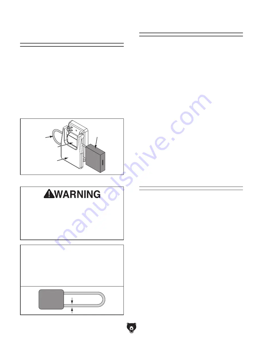
Disabling & Locking
Switch
Figure 25. Switch disabled by a padlock.
The switch can be disabled and locked by insert-
ing a padlock through the ON/START button, as
shown. Locking the switch in this manner can
prevent unauthorized operation of the machine,
which is especially important if the machine is not
stored inside an access-restricted building.
IMPORTANT: Locking the switch with a padlock
only restricts its function. It is not a substitute
for disconnecting power from the machine when
adjusting or servicing.
Shaft
Padlock
ON
/
START
Button
OFF
/
STOP
Paddle
Figure 26. Minimum lock shaft requirements.
NOTICE
The padlock shaft diameter is important to
the disabling function of the switch. With
any padlock used to lock the switch, test
the switch after installation to ensure that it
is properly disabled.
Children or untrained people can be
seriously injured by this machine. This
risk increases with unsupervised operation.
To help prevent unsupervised operation,
disable and lock the switch before leaving
machine unattended! Place key in a well-
hidden or secure location.
Содержание G0718
Страница 52: ......


