


G0555LX
(Mfg. Since 3/13)
-25-
Tool Needed
Qty
Wrench 10mm ................................................... 1
Feeler Gauge 0.016" (or Dollar Bill) ................... 1
To adjust the support bearings:
1. DISCONNECT BANDSAW FROM POWER!
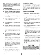
2. Familiarize yourself with the support bearing
controls shown in
Figure 29.
Knurled
Knob
Assembly Lock Bolt
Support
Bearing
Figure 29. Upper support bearing assembly and
controls.
Cap Screw
3. Loosen the guide assembly lock bolt so that
the support bearing can be rotated perpen-
dicular to the blade in the next step.
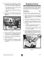
4. Rotate the blade guide assembly until the
face of the support bearing is perpendicular
to the blade, as illustrated in the
Figure 30.
Bandsaw
Blade
Support
Bearing
Figure 30. The face of the support bearing must
be perpendicular (90°) to the blade.
5. Tighten the assembly lock bolt (see Figure
29).
6. Loosen the cap screw (see Figure 29) on the
support bearing adjustment shaft.
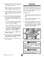
7. Use the knurled knob to position the support
bearing approximately 0.016" away from the
back of the blade, as illustrated in
Figure 31.
This can be measured with a feeler gauge or
a dollar bill.
0.016''
Figure 31. Blade should be aligned approximate-
ly 0.016" away from the bearing edge.
Adjusting Blade
Support Bearings
The support bearings are positioned behind the
blade on the blade guides and prevent it from
deflecting backward during cutting operations.
Proper adjustment of the support bearings is an
important part of making accurate cuts and keeps
the blade teeth from coming in contact with the
blade guides while cutting.
There are support bearings on the upper and
lower blade guide assemblies. Both adjust in the
same manner.
Important: The blade is tracking and tensioned
correctly before performing this procedure.
Содержание G0555LA35
Страница 12: ...12 Model G0555LA35 Mfd Since 11 17...
Страница 80: ......


