


2
WARNING: Important safety instructions
It is important for the safety of persons to follow all instructions.
SAVE these instructions
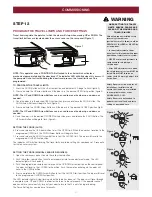
WARNING
CAUTION
WARNING
This commercial sectional door operator has been designed and tested to offer safe service provided it is installed, operated, maintained
and tested in strict accordance with the instructions and warnings contained in this manual.
Mechanical
Electrical
When you see these Safety Symbols and Signal Words on the
following pages, they will alert you to the possibility of serious
injury or death if you do not comply with the warnings that
accompany them. The hazard may come from something
mechanical or from electric shock.
When you see this Signal Word on the following pages, it will alert
you to the possibility of damage to your commercial door and/or
the commercial door operator if you do not comply with the
cautionary statements that accompany it.
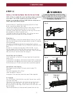
Keep commercial door balanced. Sticking or binding doors must be
repaired. Commercial doors, door springs, pulleys, brackets and their
hardware are under extreme tension and can cause serious personal
injury. Do not attempt to loosen, move or adjust them. Call for commercial
door service.
Permanently fasten all supplied labels adjacent to the wall control as a
convenient reference and reminder of safe operating procedures.
Activate operator only when the door is in full view, free of obstructions
and operator is properly adjusted. No one should enter or leave the
building while the door is in motion.
An electrician must disconnect electric power to the commercial door
operator before making repairs or removing covers.
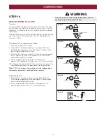
The actuating member of a biased-off switch is to be located within direct
sight of the door but away from moving parts. Unless it is key operated, it
is to be installed at a minimum height of 1500mm and not accessible to
the public.
Make sure that people who install, maintain or operate the door follow
these instructions. Keep these instructions in a safe place so that you can
refer to them quickly when you need to.
This appliance is not intended for use by persons (including children) with
reduced physical, sensory or mental capabilities, or lack of experience and
knowledge, unless they have been given supervision or instruction
concerning use of the appliance by a person responsible for their safety.
Children should be supervised to ensure that they do not play with the
appliance.
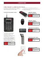
Use the commercial sectional door operator for its intended purpose. The
GLD-SDO operator is designed lifting spring-balanced sectional doors.
Disengage all existing commercial door locks to avoid damage to
commercial door. Install the wall control (or any additional push buttons) in
a location where the commercial door is visible during operation . Do not
allow children to operate push button(s) or remote transmitter(s). Serious
personal injury from a closing commercial door may result from misuse of
the operator.
Do not wear rings, watches or loose clothing while installing or servicing a
commercial door operator.
To avoid serious personal injury from entanglement, remove all ropes
connected to the commercial door before installing the door operator.
After the installation a final test of the full function of the system and the
full function of the safety devices must be done.
When operating a biased-off switch, make sure that other persons are
kept away.
The operator cannot be used with a driven part incorporating a wicket
door (unless the operator cannot be operated with the wicket door open).
If the supply cord is damaged, it must be replaced by the manufacturer,
its service agent or similarly qualified persons in order to avoid a hazard.
Do not allow children to play with operator wall controls or remote
controls. Keep remote controls away from children.
Motor may become hot during operation. Appropriate clearance and/or
shielding should be supplied by the installer to ensure any cabling, wiring
and/or other items cannot come in contact with the motor. If temperature
rise exceeds 50°C all fixed wiring insulation must be protected, for
example, by insulating sleeving having an appropriate temperature rating.
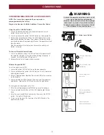
THESE ARE IMPORTANT SAFETY INSTRUCTIONS. FOLLOW ALL INSTRUCTIONS AS INCORRECT
INSTALLATION CAN LEAD TO SEVERE INJURY OR DEATH
Installation and wiring must be in compliance with your local building and
electrical codes. Connect the power supply cord only to properly earthed
mains.
Moisture and water can destroy the electronic components. Make sure
under all circumstances that water moisture or storage moisture cannot
penetrate the electronics. The same applies for openings and cable
entries.
SAFETY SYMBOL AND SIGNAL WORD REVIEW