Grifco GLD-SDO Скачать руководство пользователя страница 14

14

All Grifco remote access devices feature Se2.0 technology. This 
advanced platform cuts through interference, and ensures consistent, 
reliable, long range operation of your commercial door.

With inbuilt perpetual rolling code technology, Grifco Se2.0 

transmitters are safe and secure. All devices feature exceptional battery life, 
easy configuration and long range.

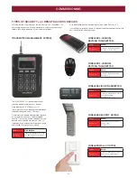
TYPES OF SE2.0 REMOTE ACCESS DEVICES

WIRELESS WALL CONTROL

WIRELESS 3-CHANNEL 
KEYRING TRANSMITTER

WIRELESS 4-CHANNEL 
KEYRING TRANSMITTER

WIRELESS VISOR TRANSMITTER

WIRELESS SECURITY KEYPAD

Part No.

E138G

Description

2-channel transmitter for wall 
mounting on internal walls
Se2.0

Part No.

E840G

Description

Wireless keypad for external 
keyless entry
Se2.0

Part No.

E943G

Description

3-channel transmitter for vehicle 
or forklift mounting
Se2.0

Part No.

E945G

Description

3-channel keyring transmitter
Se2.0

Part No.

E960G

Description

4-channel keyring transmitter.
Se2.0 / S

Part No.

STAR1000EVO

Description

Transmitter management for up 
to 1,000 Se2.0 remote 
access devices

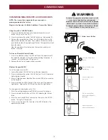
TRANSMITTER MANAGEMENT SYSTEM

The STAR1000EVO is ideal for applications 
requiring multiple remote access devices.

It supports up to 1,000 Se2.0 
transmitters which can be programmed through 
the onboard keypad and LCD screen.

Transmitters can be added or deleted singularly 
or in groups via an access code for added 
security. Transmitters can be coded offsite and 
backed up via an onboard memory chip. It is 
supplied with an antenna for exceptional range 
and is rated IP44 for water resistance.
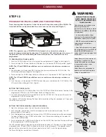
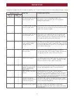
COMMISSIONING

Содержание GLD-SDO

Страница 1: ...BY A TRAINED TECHNICIAN ONLY This operator is compatible with Security 2 0 accessories OPERATOR SUPPLIED WITH GRIFCO MONITORED ENTRAPMENT PROTECTION OPERATOR SUPPLIED WITH GRIFCO MONITORED ENTRAPMENT...

Страница 2: ...supervision or instruction concerning use of the appliance by a person responsible for their safety Children should be supervised to ensure that they do not play with the appliance Use the commercial...

Страница 3: ...L HEADER BRACKET 8 POSITION THE OPERATOR 9 MOUNT THE OPERATOR TO THE CEILING 9 FASTEN THE DOOR BRACKET 9 ATTACH DOOR ARM TO TROLLEY 10 TESTING AND OPERATING THE MANUAL RELEASE 10 COMMISSIONING 11 PROG...

Страница 4: ...erator Width 200mm Rail Width 88mm Total installed dimensions GLD R2 4M 3 372mm L x 150mm H x 200mm W GLD R3 0M 3 972mm L x 150mm H x 200mm W Compliance AS NZS 60335 1 AS NZS 60335 2 103 Transmitter S...

Страница 5: ...us programming modes 6 External Accessory Power 30 Vdc 50mA available Constant supply no low standby unregulated 7 Terminal Blocks Used to configure external accessories See chart below for the functi...

Страница 6: ...e Mounting Hardware Cable Clips x 4 Safety Beams Grifco 4 Channel Transmitter 1 Wall plug 2 R clip 3 Hexagonal head screw M8x25 4 Hexagonal head screw M8x20 5 Clevis pin 8mm 6 Clevis pin 6mm 7 Screw S...

Страница 7: ...head screw into either side of the rail 1 Slide screws 300mm from end of rail 2 Position the rail drive sprocket inside the rail over the operator motor shaft 2 and push down to install Ensure motor...

Страница 8: ...e the Header Bracket using the most suitable variation of holes If using the wood screws provided uses a 4 5mm pilot drill If securing to a metal fixture self tapping tek screws may be more suitable S...

Страница 9: ...ting directly onto the ceiling drill appropriate holes through the top of the rail Use a minimum of 2 screws to fix to the ceiling Screw the rail directly into a structural support on the ceiling 4 En...

Страница 10: ...manual release Instruction Label around the cord as shown below DO NOT USE THE RED HANDLE TO OPEN AND CLOSE THE DOOR To operate the Manual Release The door should be fully closed if possible 1 Diseng...

Страница 11: ...e setting has now been set Proceed to test safety reverse system SETTING THE FORCE MANUAL LEARN IF REQUIRED 1 Open the rear access panel Locate the yellow Learn button 2 Push the yellow Learn button t...

Страница 12: ...rail extrusion and secure with the 4 supplied cable clips to ensure cable does not come loose Mount a cable clip at either end of the rail and either side of the rail figure 4 Remove Power from the Op...

Страница 13: ...3 eg twice for 20 seconds Press the DOWN arrow button to reduce if needed 4 Press and release the PROG button to save this time figure 4 LED indicator light will flash once TTC is now activated TEST...

Страница 14: ...eypad for external keyless entry Security 2 0 Part No E943G Description 3 channel transmitter for vehicle or forklift mounting Security 2 0 Part No E945G Description 3 channel keyring transmitter Secu...

Страница 15: ...ARN button on the door operator 2 Press and release the yellow LEARN button The LED indicator light will glow steadily 3 Enter a 4 digit personal identification number PIN of your choice on the keypad...

Страница 16: ...losing door to open and prevents an open door from closing 4 The operator lights will turn on under the following conditions when the operator is initially plugged in when power is restored after inte...

Страница 17: ...Beams are flashing correct the alignment If operator light does not flash and it is a new installation repeat Programming the Travel Limits 8 Operator strains Door may be unbalanced or springs are bro...

Страница 18: ...ce centre 1 6 Door continues to move after the motor stops RPM pulses have been detected after motor has turned off Possible broken spring Check the door is correctly balanced and not creeping up or d...

Страница 19: ...er cord 026B0181 Passpoint assembly 002A1965 Transformer 041A4027 LED module 041A4002 1 Chassis cover assembly 002A1964 Motor shaft adapter metal 041A4017 1 Rail Replacement Parts Position tab chain 0...

Страница 20: ...eration maintenance and testing of the Unit or of any product with which the Unit is used 2 any attempt by a person other than an authorised installer to change settings repair dismantle reinstall or...

Отзывы: