Installation Instructions
Introduction
This humidity transmitter uses a highly accurate and reliable Thermoset
Polymer based capacitance humidity sensor and state-of-the-art digital
linearization and temperature compensated circuitry to monitor
humidity levels in a duct. The humidity sensor is encapsulated in a 60
micron HDPE filter at the end of a 230 mm (9”) S/S probe and a compact
enclosure. An optional temperature sensor is available.
Before Installation
Read these instructions carefully before installing and commissioning
the RH transmitter. Failure to follow these instructions may result in
product damage. Do not use in an explosive or hazardous environment,
with combustible or flammable gases, as a safety or emergency stop
device or in any other application where failure of the product could
result in personal injury.
Take electrostatic discharge precautions
during installation and do not exceed the device ratings.
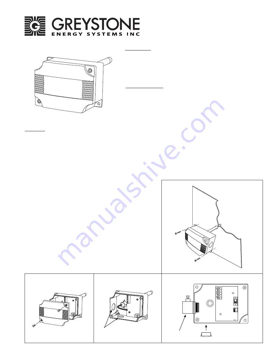
Figure 1
Figure 2
Figure 4
Figure 3
EMT/Cable Gland Connection Holes
EMT Connector
Connection Hole Cap
A foam gasket is provided on the back of the enclosure that provides a
tight seal against any air leaks.
Using a Phillips screwdriver, remove the (2) screws, as shown in Figure 2.
Remove cover and set aside with screws for re-installing after wiring
and set up.
Two 21 mm (0.8125”) holes are provided for connection of either
12.77mm (0.5” ) EMT or a cable gland style connector as shown in Figure 3.
Insert the EMT or cable gland connector through the hole and securely
fasten using a locknut. If only one connection hole is required, use the
included hole cap to cap off the unused one as shown in Figure 4.
Special care must be taken not to damage any internal components
during installation.
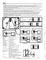
Make wire connections as per the “Wiring” illustrations on Page 2.
Once wiring and set up are complete, re-install cover and tighten the (2)
screws using a Phillips screwdriver.
Mounting
The tranmitter installs directly into any air duct with a minimum width/diameter of 25.5 cm (10”). Select a suitable installation
area in the middle of the duct wall. To achieve the best reading, do not place in an area where air stratification may be
present.
Mount the sensor at least 1.5 m (5 ‘ ) in either direction from elbows, dampers, filters or other duct restric-
tions. Avoid areas where the transmitter is exposed to vibrations or rapid temperature changes.
Once a suitable spot is selected, drill a 15 -20 mm (0.6” - .75“ ) hole for the probe.
Slide the probe in the drilled hole until the enclosure is flush against the duct. The airflow direction is not important. Secure
the enclosure to the duct with (2) #10 x 1” (25 mm) self tapping screws (Not provided). Tighten screws until the enclosure is
tight against the duct and that there is no movement of the enclosure as shown in Figure 1.
RH200A RH Transmitter
Greystone Energy Systems, Inc. 150 English Drive, Moncton, NB E1E 4G7 Canada Tel: +1-506-853-3057 Tollfree (North America): +1-800-561-5611 Fax: +1-506-853-6014
Email: [email protected] Web: www.greystoneenergy.com


