background image

16

SPECIFICATIONS

Display:

3-1/2 digit LCD (liquid crystal display) with a maximum reading
of 1999

Polarity Indication:

positive implied, negative indicated

Sampling:

3 times per second

Low Battery Indication:

L

B

 is displayed when the battery voltage drops below the operating

voltage

Overload Indication:

“1” at the left side of the display

Operating Temperature

and Humidity:

 32

°

 F – 104

°

 F (0

°

 C – 40

°

 C), 80% relative humidity maximum

Storage Temperature

and Humidity:

14

°

F – 122

°

F (-10

°

C – 50

°

 C) 80% relative humidity maximum

Power Requirements:

9V battery (006P) Alkaline

Fuse:

0.5 A/250V

Dimensions:

7.24 x 3.3 x 1.61 in. (18.4 x 8.4 x 4.1 cm)

Weight:

10.48 oz (297 g)

Accuracy:

+/– (% of r number of digits)

see the following specification tables for accuracies
of specific functions

Содержание 93-603

Страница 1: ...Failure to understand how to safely operate the meter could result in an accident causing serious injury or death This meter should only be operated by qualified personnel 93 603 MULTIMETER OPERATION...

Страница 2: ...ion for Use 8 Voltage Measurement 9 Current Measurement 10 Resistance Measurement 11 Continuity Check 12 Diode Check 13 Battery Check 14 Transistor Check 15 Specifications 16 19 Maintenance Replacing...

Страница 3: ...in severe personal injury or death SAFETY ALERT SYMBOL The symbol above is used to call your attention to instructions concerning your personal safety Watch for this symbol It points out important saf...

Страница 4: ...ure more than 20 amps Do not connect the meter to a source of voltage or current when the range selector is in an position the position the position or the hFE position Failure to observe these warnin...

Страница 5: ...erly rated fuses when replacement is necessary See the Specifications section of this manual Do not perform any service or maintenance other than as described in this manual Replace weak or discharged...

Страница 6: ...rpose meter with the following measurement functions and measurement ranges AC Voltage 0 750 volts DC Current 0 20 amps DC Voltage 0 1000 volts Resistance 0 20 megohms Continuity Check Diode Check Bat...

Страница 7: ...ptacle receptacles for the emitter E base B and collector C leads of NPN or PNP transistors 4 20A Input Terminal positive input terminal for DC current measurements between 200 mA and 20 A 5 mA Input...

Страница 8: ...rm as expected refer to the following troubleshooting list until the problem is solved 1 Test leads are not fully plugged into the input terminals 2 The test lead tips or test lead connectors are corr...

Страница 9: ...in severe injury or death Voltage Measurement 1 Plug the black test lead into the COM input terminal and plug the red test lead into the V BAT input terminal 2 Set range selector to the appropriate D...

Страница 10: ...terminal 4 Set range selector to the appropriate DCA range Note When measuring an unknown current start at the 20 A range 5 Connect the test leads to the circuit 6 Apply power to the circuit under tes...

Страница 11: ...ed test lead into the V BAT input terminal 3 Set the range selector to the 200 position 4 Touch the test lead tips together The meter should display 0 If the meter does not display a 0 make a note of...

Страница 12: ...sent 2 Plug the black test lead into the COM input terminal and plug the red test lead into the V BAT input terminal 3 Set range selector to the position 4 Touch the test leads to the circuit under te...

Страница 13: ...he red test lead into the V BAT input terminal 3 Set range selector to the position 4 Touch the test leads to the diode under test and read the display The expected display is approximately as follows...

Страница 14: ...the voltage of a 9 volt battery set the range selector to 9V BATT TEST 3 Touch the red test probe to the positive terminal of the battery and touch the black test probe to the negative terminal of th...

Страница 15: ...lay 4 Refer to the transistor manufacturer s specifications for the expected hFE reading Disconnect the test leads from the component or circuit under test before changing the position of the range se...

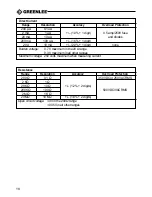
Страница 16: ...tage Overload Indication 1 at the left side of the display Operating Temperature and Humidity 32 F 104 F 0 C 40 C 80 relative humidity maximum Storage Temperature and Humidity 14 F 122 F 10 C 50 C 80...

Страница 17: ...1 digit 500 VDC or 350 VAC RMS 2 V 1 mV 20 V 10 mV 0 7 1 digit 1100 VDC or 800 VAC RMS 200 V 100 mV 1000 V 1 V Input Impedance 10 M AC Voltage 50 Hz 400 Hz Range Resolution Accuracy Overload Protecti...

Страница 18: ...t none Burden voltage 0 7 V maximum in the 20 A range 0 3 V maximum in all other ranges Maximum voltage 250 volts maximum when measuring current Resistance Range Resolution Accuracy Overload Protectio...

Страница 19: ...ntinuity Check Range Continuity Threshold Continuity Indication Overload Protection less than 40 Audible Buzzer 250 VDC VAC RMS Open circuit voltage 3 VDC Transistor Check Range hFE Range Test Current...

Страница 20: ...OFF Remove the test leads from the meter 2 Remove the protective boot from the meter 3 Slide off the battery and fuse compartment door 4 Remove and replace the battery or fuse s as necessary 5 Replac...

Страница 21: ...ditions contained in Greenlee s standard one year limited warranty For all Test Instrument repairs ship units Freight Prepaid to Greenlee Textron Inc at 4411 Boeing Drive Rockford IL 61109 2932 USA Ma...

Страница 22: ...mult metro El hecho de no comprender la forma segura de operar el medidor podr a ocasionar lesiones graves o incluso la muerte Este medidor s lo deber ser usado por personal calificado MULT METRO 93 6...

Страница 23: ...r sticas 28 Operaci n Preparaci n para el uso 29 Medici n de voltaje 30 Medici n de corriente 31 Medici n de resistencia 32 Revisi n de continuidad 33 Revisi n de diodos 34 Revisi n de bater as 35 Rev...

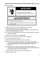
Страница 24: ...de seguridad importantes y significa ATENCI N Tenga cuidado Est en riesgo su seguridad Lea el mensaje que aparece despu s del s mbolo y tenga presente la posibilidad de lesiones o incluso la muerte R...

Страница 25: ...VCD No intente medir m s de 20 amperios No conecte el medidor a una fuente de voltaje o corriente si el selector de intervalo est en la posici n o hFE La inobservancia de estas advertencias puede ocas...

Страница 26: ...eemplace el fusible nicamente con otros de clasificaci n apropiada Consulte la secci n Especificaciones de este manual No lleve a cabo ninguna actividad de servicio o mantenimiento que no est descrita...

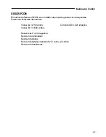
Страница 27: ...neral con las siguientes funciones e intervalos de medici n Voltaje CA 0 750 voltios Corriente CD 0 a 20 amperios Voltaje CD 0 1000 voltios Resistencia 0 a 20 megaohms Revisi n de continuidad Revisi n...

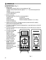
Страница 28: ...de 1 5 y 9 voltios Revisi n de transistores 3 Recept culo para transistores Recept culos para las puntas emisora E base B y colectora C de transistores NPN o PNP 4 Terminal de entrada 20A Terminal de...

Страница 29: ...lista de resoluci n de problemas presentada a continuaci n para detectar la causa del problema 1 Los cables de prueba no est n bien conectados en los terminales de entrada 2 Las puntas o los conector...

Страница 30: ...cable de prueba rojo al terminal de entrada V BAT 2 Mueva el selector de intervalo al intervalo DCV VCD o ACV VCA apropiado Nota Al medir un voltaje desconocido comience en el intervalo m s alto 3 Po...

Страница 31: ...esconocida comience en el intervalo 20A 5 Conecte los cables de prueba al circuito 6 Aplique energ a al circuito que probar y lea el valor en la pantalla Nota Si la definici n de la lectura no es sati...

Страница 32: ...a rojo al terminal de entrada V BAT 3 Mueva el selector de intervalo a la posici n 200 4 Ponga en contacto las puntas de los dos cables de prueba El medidor deber indicar 0 Si no aparece este valor an...

Страница 33: ...advertencia puede ocasionar lesiones graves o incluso la muerte 1 Apague y desconecte el suministro de energ a Cerci rese de que todos los condensadores est n descargados No debe haber voltaje presen...

Страница 34: ...a V BAT 3 Mueva el selector de intervalo a la posici n 4 Ponga los cables de prueba en contacto con el diodo que probar y lea el valor en la pantalla Las lecturas que deben aparecer en la pantalla son...

Страница 35: ...oltaje de una bater a de 9 voltios mueva el selector a la posici n 9V BATT TEST 3 Ponga el cable de prueba rojo en contacto con el terminal positivo de la bater a y el cable de prueba negro en contact...

Страница 36: ...sici n hFE La inobservancia de esta advertencia puede ocasionar lesiones graves o incluso la muerte REVISI N DE TRANSISTORES 1 Mueva el selector de intervalo a la posici n hFE apropiada NPN o PNP 2 In...

Страница 37: ...1 en el lado izquierdo de la pantalla Temperatura y humedad operativas 0 C 40 C 32 F 104 F 80 de humedad relativa m xima Temperatura y humedad de almacenamiento 10 C 50 C 14 F 122 F 80 de humedad rela...

Страница 38: ...D o 350 VCA RMS 2 V 1 mV 20 V 10 mV 0 7 1 d gito 1100 VCD u 800 VCA RMS 200 V 100 mV 1000 V 1 V Impedancia de entrada 10 M Voltaje CA 50 Hz 400 Hz Intervalo Definici n Precisi n Protecci n contra sobr...

Страница 39: ...to Ninguna Voltaje de carga 0 7 V m ximo en el intervalo de 20 A 0 3 V m ximo en los dem s intervalos Voltaje m ximo 250 V m ximo al medir corriente Resistencia Intervalo Definici n Precisi n Protecci...

Страница 40: ...nici n Corriente de carga Resistencia de carga 1 5 V 1 mV 150 mA 10 9 V 10 mV 9 mA 1 K Revisi n de continuidad Intervalo Umbral de continuidad Indicador de continuidad Protecci n contra sobrecargas Me...

Страница 41: ...ci n OFF Desconecte los cables de prueba del medidor 2 Quite la funda protectora del medidor 3 Abra el compartimiento de la bater a y el fusible 4 Saque y reemplace la bater a o el fusible seg n se re...

Страница 42: ...o de duraci n Para reparaci n de instrumentos de medici n env e las unidades con flete pagado a Greenlee Textron Inc at 4411 Boeing Drive Rockford IL 61109 2932 EE UU Marque todos los paquetes Atenci...

Страница 43: ...de ne pas comprendre les instructions de fonctionnement et de s curit de cet instrument risque de provoquer un accident pouvant entra ner de graves blessures ou la mort Cet instrument de mesure ne do...

Страница 44: ...ation au relever d utilisation 50 Mesure de la tension 51 Mesure de l intensit du courant 52 Mesure de la r sistance 53 Contr le de continuit 54 Contr le de diode 55 Contr le de batterie 56 Contr le d...

Страница 45: ...cart s PEUVENT entra ner des accidents graves ou la mort Dangers imm diats qui s ils ne sont pas cart s ENTRA NENT des accidents graves ou la mort SYMBOLE D ALERTE POUR LA S CURIT Le symbole ci dessu...

Страница 46: ...urer une intensit sup rieure 20 A Ne pas connecter l instrument de mesure une source de tension ou de courant lorsque le s lecteur de plage se trouve sur ou hFE L inobservation de ces pr cautions peut...

Страница 47: ...n cessaire Voir la section Caract ristiques techniques dans ce manuel N effectuez aucune r paration ou maintenance autres que celles d crites dans ce manuel Remplacez les batteries faibles ou d charg...

Страница 48: ...re polyvalent comprenant les fonctions et capacit s de mesure suivantes Tension c a 0 750 volts Courant continu 0 20 A Tension c c 0 1 000 volts R sistance 0 20 M Contr le de continuit Contr le de dio...

Страница 49: ...eries de 1 5 V et 9 V Contr le du transistor 3 Fiches pour transistors fiches pour les bornes de l metteur E de la base B et du collecteur C des transistors NPN ou PNP 4 Borne d entr e 20 A borne d en...

Страница 50: ...nts d sir es renvoyez la liste de la r solution des probl mes suivante jusqu ce que la probl me est r soudue 1 Le conducteur d essai n est pas connect compl tement dans la borne d entr e 2 Le bout ou...

Страница 51: ...satisfaisante d connecter l instrument de mesure du circuit et s lectionner la plage imm diatement inf rieure Connecter nouveau l instrument de mesure au circuit et lire l affichage R p ter cette pro...

Страница 52: ...tension inconnue commencer avec la plage 20 A 5 Connecter les c bles d essai au circuit 6 Mettre le circuit objet de l essai sous tension et lire l affichage Remarque Si la r solution de l affichage...

Страница 53: ...bles d essai avec l l ment objet de l essai et lire l affichage 7 Soustraire la valeur obtenue l tape 4 de la valeur indiqu e sur l affichage pour obtenir la valeur r elle de la r sistance Remarque Si...

Страница 54: ...tion de ce pr caution peut entra ner des accidents graves ou la mort 1 Mettre l unit hors tension et couper l arriv e de courant S assurer que tous les condensateurs sont d charg s Aucun l ment ne doi...

Страница 55: ...ource de tension ou de courant lorsque le s lecteur de plage se trouve sur la position L inobservation de ce pr caution peut entra ner des accidents graves ou la mort Remarque Toute autre indication r...

Страница 56: ...our mesurer la tension d une batterie de 9 V positionner le s lecteur de plage sur 9 V BATT TEST Essai de la batterie de 9 V 3 Mettre en contact le stylet de v rification rouge avec la borne positive...

Страница 57: ...trouve sur la position hFE L inobservation de ce pr caution peut entra ner des accidents graves ou la mort CONTR LE DU TRANSISTOR 1 Positionner le s lecteur de plage sur la position hFE appropri e NPN...

Страница 58: ...de fonctionnement Indicateur de surcharge 1 gauche de l affichage Humidit et temp rature de fonctionnement 0 C 40 C 32 F 104 F humidit relative maximale 80 Humidit et temp rature d entreposage 10 C 5...

Страница 59: ...50 V c a efficaces 2 V 1 mV 20 V 10 mV 0 7 1 chiffre 1 100 V c c ou 800 V c a efficaces 200 V 100 mV 1 000 V 1 V Imp dance d entr e 10 M Tension en courant alternatif 50 Hz 400 Hz Plage R solution Pr...

Страница 60: ...rcuit ouvert 3 V pour la plage 200 0 35 V pour toutes les autres plages Courant continu Plage R solution Pr cision Protection contre les surcharges 200 A 0 1 A 2 mA 1 A 1 1 chiffre Fusible 0 5 A 250 V...

Страница 61: ...nuit Plage Seuil de continuit Indicateur de continuit Protection contre les surcharges moins de 40 Sonnette audible 250 V c c V c a efficaces Tension de circuit ouvert 3 V c c Contr le du transistor P...

Страница 62: ...instrument de mesure 2 Retirer la gaine protectrice de l instrument 3 Faire glisser la porte du compartiment du fusible et de la batterie pour la retirer 4 Retirer et remplacer la batterie ou le s fus...

Страница 63: ...n de Greenlee Pour toutes les r parations d instruments de mesure exp diez l appareil en port pay l adresse suivante Greenlee Textron Inc 4411 Boeing Drive Rockford IL 61109 2932 tats Unis Sur tous le...

Страница 64: ...Greenlee Textron Inc Subsidiary of Textron Inc Greenlee Textron Inc Filiale de Textron Inc Greenlee Textron Inc Subsidiaria de Textron Inc 4455 Boeing Drive Rockford IL 61109 2988 USA...

Отзывы: