FC8600-UM-251-9370 3-3
3 OPERATIONS
3.2 Reading the Screen (LCD)
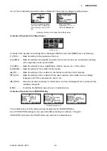
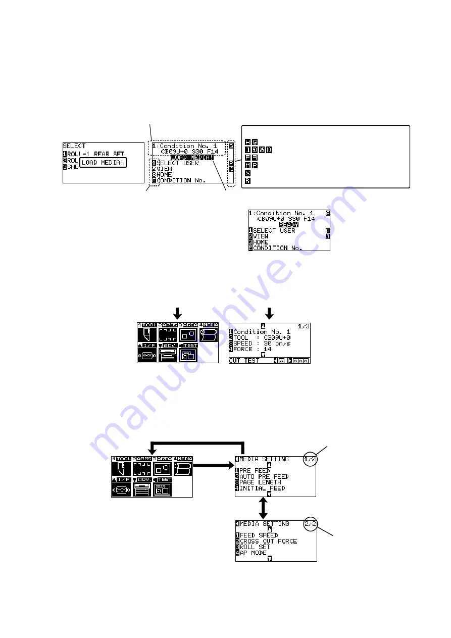
Information reflecting the status will be displayed in the screen of the control panel.
Name of the button and corresponding function is displayed on the screen when a function is allocated to the
button on the control panel. Button name will be displayed in reverse when the button is enabled.
Following items are displayed in the default screen.
Tool condition currently using
Corresponding button name of control panel
Set condition of media
(READY status: It will display "READY" when the media is loaded)
Display of setting condition
Command: HP-GL/GP-GL
Step size:
0.1 mm/50 µm/25 µm/10 µm
Rotate/mirror: Rotate 90 degrees/mirror
Priority:
Manual priority/program priority
Sort:
Display when sort is on
Prefeed:
Display when automatic media feed is on
Media set lever raised
Media set lever lowered
Display of Default Screen
(Valid button is displayed in reverse)
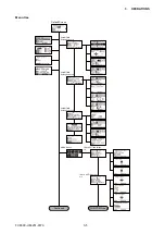
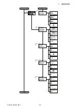
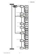
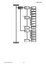
Screen to set the corresponding conditions is displayed when the [MENU] key or [CONDITION] key are
pressed.
MENU
CONDITION
MENU screen
CONDITION screen
It will return to default
screen when [MENU]
key is pressed while
displaying MENU
screen.
It will return to
default screen when
[CONDITION] key is
pressed while displaying
CONDITION screen.
MENU screen displayed by button operation
Page number is displayed in the upper right corner of the screen if there are too many settings or selection
that will need multiple pages to display.
Press the position (
pq
) key to move different page.
POSITION(
t
) key
[4] key
Page number
Page number
POSITION(?? ) key
Example of moving page and operation button
Содержание FC8600-100
Страница 1: ...CUTTING PLOTTER SERVICE MANUAL FC8600 60 75 100 130 160 FC8600 UM 251 07 9370 ...
Страница 2: ......
Страница 4: ...FC8600 UM 251 9370 II ...
Страница 32: ......
Страница 103: ...FC8600 UM 251 9370 7 43 7 ADJUSTMENT ...
Страница 118: ...FC8600 UM 251 9370 8 15 8 TROUBLESHOOTING 11 When testing is completed turn off the power to the plotter ...
Страница 124: ...FC8600 UM 251 9370 9 2 9 PARTS LIST Outer Casing 4 6 2 3 9 13 11 12 14 15 10 1 16 8 7 5 ...
Страница 131: ...FC8600 UM 251 9370 9 9 9 PARTS LIST Main Frame 1 3 4 5 7 8 9 10 11 12 6 2 15 16 13 14 20 21 22 17 18 19 ...
Страница 141: ...FC8600 UM 251 9370 10 3 10 BLOCK DIAGRAMS AND CIRCUIT DIAGRAMS 10 2 2 Main Board CONNECTOR ...
Страница 142: ...FC8600 UM 251 9370 10 4 10 BLOCK DIAGRAMS AND CIRCUIT DIAGRAMS 10 2 3 Main Board MOTOR DRIVER ...
Страница 143: ...FC8600 UM 251 9370 10 5 10 BLOCK DIAGRAMS AND CIRCUIT DIAGRAMS 10 2 4 Main Board FPGA ...
Страница 144: ...FC8600 UM 251 9370 10 6 10 BLOCK DIAGRAMS AND CIRCUIT DIAGRAMS 10 2 5 Main Board I F ...
Страница 145: ...FC8600 UM 251 9370 10 7 10 BLOCK DIAGRAMS AND CIRCUIT DIAGRAMS 10 2 6 Main Board MEMORY ...
Страница 146: ...FC8600 UM 251 9370 10 8 10 BLOCK DIAGRAMS AND CIRCUIT DIAGRAMS 10 2 7 Main Board Power When the LAN is connected ...
Страница 147: ...FC8600 UM 251 9370 10 9 10 BLOCK DIAGRAMS AND CIRCUIT DIAGRAMS 10 2 8 LAN Board ...
Страница 148: ...FC8600 UM 251 9370 10 10 10 BLOCK DIAGRAMS AND CIRCUIT DIAGRAMS 10 2 9 Light Pointer ...
Страница 149: ...FC8600 UM 251 9370 10 11 10 BLOCK DIAGRAMS AND CIRCUIT DIAGRAMS 10 2 10Pen Relay Board ...
Страница 151: ...FC8600 UM 251 9370 10 13 10 BLOCK DIAGRAMS AND CIRCUIT DIAGRAMS 10 2 13Control Panel Board ...
Страница 152: ...FC8600 UM 251 9370 10 14 10 BLOCK DIAGRAMS AND CIRCUIT DIAGRAMS 10 2 14Cam Sensor Board ...

