FC8600-UM-251-9370 16
8 TROUBLESHOOTING
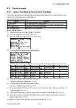
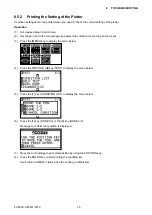
8.5.2 Printing the Setting of the Plotter
Condition setting list can be printed when you need to check the current setting of the plotter.
Operation
(1) Set a paper larger than A3 size.
(2) Set the pen tool to the tool carriage and select the condition where the pen tool is set.
(3) Press the [MENU] key to display the menu below.
(4) Press the POSITION (
t
) key (TEST) to display the menu below.
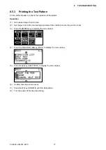
(5) Press the [1] key (CONDITION LIST) to display the menu below.
(6) Press the [1] key (DONE 1/2) or the [2] key (DONE 2/2).
Message to confirm tool position is displayed.
(7) Move the tool carriage to print start position by using the POSITION key.
(8) Press the ENTER key to start printing the condition list.
It will return to READY status when the printing is completed.
Содержание FC8600-100
Страница 1: ...CUTTING PLOTTER SERVICE MANUAL FC8600 60 75 100 130 160 FC8600 UM 251 07 9370 ...
Страница 2: ......
Страница 4: ...FC8600 UM 251 9370 II ...
Страница 32: ......
Страница 103: ...FC8600 UM 251 9370 7 43 7 ADJUSTMENT ...
Страница 118: ...FC8600 UM 251 9370 8 15 8 TROUBLESHOOTING 11 When testing is completed turn off the power to the plotter ...
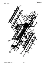
Страница 124: ...FC8600 UM 251 9370 9 2 9 PARTS LIST Outer Casing 4 6 2 3 9 13 11 12 14 15 10 1 16 8 7 5 ...
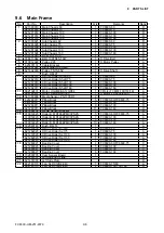
Страница 131: ...FC8600 UM 251 9370 9 9 9 PARTS LIST Main Frame 1 3 4 5 7 8 9 10 11 12 6 2 15 16 13 14 20 21 22 17 18 19 ...
Страница 141: ...FC8600 UM 251 9370 10 3 10 BLOCK DIAGRAMS AND CIRCUIT DIAGRAMS 10 2 2 Main Board CONNECTOR ...
Страница 142: ...FC8600 UM 251 9370 10 4 10 BLOCK DIAGRAMS AND CIRCUIT DIAGRAMS 10 2 3 Main Board MOTOR DRIVER ...
Страница 143: ...FC8600 UM 251 9370 10 5 10 BLOCK DIAGRAMS AND CIRCUIT DIAGRAMS 10 2 4 Main Board FPGA ...
Страница 144: ...FC8600 UM 251 9370 10 6 10 BLOCK DIAGRAMS AND CIRCUIT DIAGRAMS 10 2 5 Main Board I F ...
Страница 145: ...FC8600 UM 251 9370 10 7 10 BLOCK DIAGRAMS AND CIRCUIT DIAGRAMS 10 2 6 Main Board MEMORY ...
Страница 146: ...FC8600 UM 251 9370 10 8 10 BLOCK DIAGRAMS AND CIRCUIT DIAGRAMS 10 2 7 Main Board Power When the LAN is connected ...
Страница 147: ...FC8600 UM 251 9370 10 9 10 BLOCK DIAGRAMS AND CIRCUIT DIAGRAMS 10 2 8 LAN Board ...
Страница 148: ...FC8600 UM 251 9370 10 10 10 BLOCK DIAGRAMS AND CIRCUIT DIAGRAMS 10 2 9 Light Pointer ...
Страница 149: ...FC8600 UM 251 9370 10 11 10 BLOCK DIAGRAMS AND CIRCUIT DIAGRAMS 10 2 10Pen Relay Board ...
Страница 151: ...FC8600 UM 251 9370 10 13 10 BLOCK DIAGRAMS AND CIRCUIT DIAGRAMS 10 2 13Control Panel Board ...
Страница 152: ...FC8600 UM 251 9370 10 14 10 BLOCK DIAGRAMS AND CIRCUIT DIAGRAMS 10 2 14Cam Sensor Board ...

