FC8600-UM-251-9370 8-14
8 TROUBLESHOOTING
8.5
Service mode
8.5.1
Sensor Test Mode & Panel Switch Test Mode
This mode checks the sensor status and the control panel switch status. If there is a bad sensor you will
observe one of the symptoms in the table below.
Please check the relevant sensor(s).
Sensor
Symptom
Y home sensor
The pen block hits the right side plate.
Cam sensor
The plotter displays “LOAD MEDIA!” when media is already loaded.
Pinch roller sensor
The pen block hits the left side plate.
+X, -X media sensor
Media drops out of the plotter.
How to test the sensors
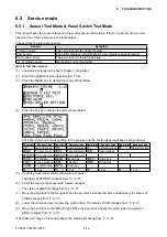
(1) Load an A2 or larger size sheet of paper in the plotter.
(2) Enter the adjustment menu (see Section 7.3.4).
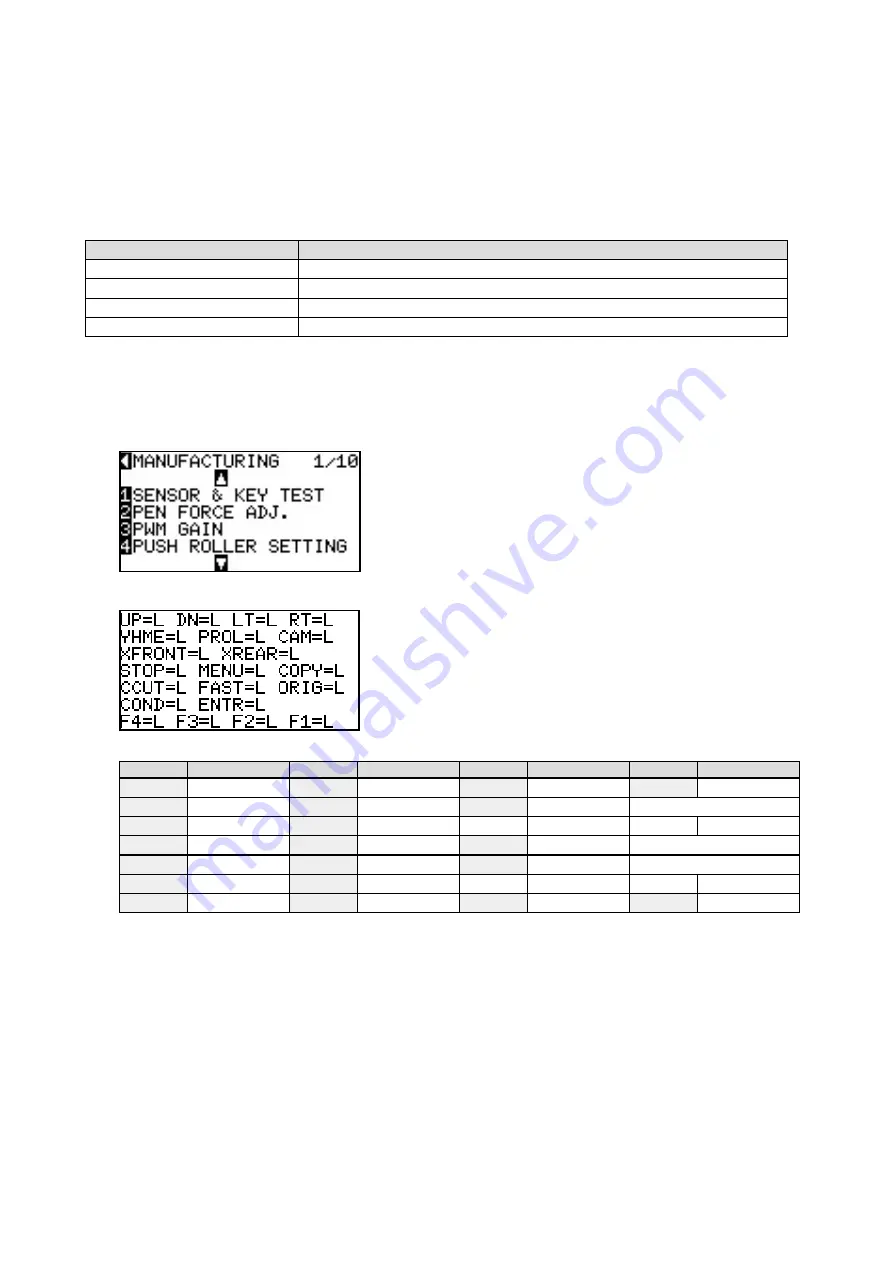
(3) Press the MENU key to display the menu shown below.
(4) Press the F1 key to display the menu shown below.
Each short forms are corresponding to the sensors and the control panel switches as shown below.
Short form Sensor or key Short form Sensor or key Short form Sensor or key Short form Sensor or key
UP
Up arrow key DN
Down arrow key LT
Left arrow key RT
Right arrow key
YHME
Y home sensor PROL
Pinch roller sensor CAM
Cam sensor
XFRONT Front media sensor XREAR Rear media sensor
STOP
STOP key
MENU
Menu key
COPY
Copy key
CCUT
Cross Cut key FAST
Fast key
ORIG
Origin key
COND
Condition key ENTR
Enter key
F4
4 key
F3
3 key
F2
2 key
F1
1 key
(5) Cover the front media sensor with a piece of paper.
The status of XFRONT changes from “L” to “H”.
(6) Cover the rear media sensor with a piece of paper.
The status of XREAR changes from “L” to “H”.
(7)
Move the pen block to the far right. When the pen block reaches the home position flag, the status of
YHME changes from “L” to “H”.
(8) Lower the media set lever to raise the pinch rollers. The status of CAM changes from “L” to “H”.
(9) Move the pen block to the left and right. When the pen block crosses the pinch roller, the status of
PROL changes from “L” to “H”.
(10) Press each key on the control panel; the status will change from “L” to “H”.
Содержание FC8600-100
Страница 1: ...CUTTING PLOTTER SERVICE MANUAL FC8600 60 75 100 130 160 FC8600 UM 251 07 9370 ...
Страница 2: ......
Страница 4: ...FC8600 UM 251 9370 II ...
Страница 32: ......
Страница 103: ...FC8600 UM 251 9370 7 43 7 ADJUSTMENT ...
Страница 118: ...FC8600 UM 251 9370 8 15 8 TROUBLESHOOTING 11 When testing is completed turn off the power to the plotter ...
Страница 124: ...FC8600 UM 251 9370 9 2 9 PARTS LIST Outer Casing 4 6 2 3 9 13 11 12 14 15 10 1 16 8 7 5 ...
Страница 131: ...FC8600 UM 251 9370 9 9 9 PARTS LIST Main Frame 1 3 4 5 7 8 9 10 11 12 6 2 15 16 13 14 20 21 22 17 18 19 ...
Страница 141: ...FC8600 UM 251 9370 10 3 10 BLOCK DIAGRAMS AND CIRCUIT DIAGRAMS 10 2 2 Main Board CONNECTOR ...
Страница 142: ...FC8600 UM 251 9370 10 4 10 BLOCK DIAGRAMS AND CIRCUIT DIAGRAMS 10 2 3 Main Board MOTOR DRIVER ...
Страница 143: ...FC8600 UM 251 9370 10 5 10 BLOCK DIAGRAMS AND CIRCUIT DIAGRAMS 10 2 4 Main Board FPGA ...
Страница 144: ...FC8600 UM 251 9370 10 6 10 BLOCK DIAGRAMS AND CIRCUIT DIAGRAMS 10 2 5 Main Board I F ...
Страница 145: ...FC8600 UM 251 9370 10 7 10 BLOCK DIAGRAMS AND CIRCUIT DIAGRAMS 10 2 6 Main Board MEMORY ...
Страница 146: ...FC8600 UM 251 9370 10 8 10 BLOCK DIAGRAMS AND CIRCUIT DIAGRAMS 10 2 7 Main Board Power When the LAN is connected ...
Страница 147: ...FC8600 UM 251 9370 10 9 10 BLOCK DIAGRAMS AND CIRCUIT DIAGRAMS 10 2 8 LAN Board ...
Страница 148: ...FC8600 UM 251 9370 10 10 10 BLOCK DIAGRAMS AND CIRCUIT DIAGRAMS 10 2 9 Light Pointer ...
Страница 149: ...FC8600 UM 251 9370 10 11 10 BLOCK DIAGRAMS AND CIRCUIT DIAGRAMS 10 2 10Pen Relay Board ...
Страница 151: ...FC8600 UM 251 9370 10 13 10 BLOCK DIAGRAMS AND CIRCUIT DIAGRAMS 10 2 13Control Panel Board ...
Страница 152: ...FC8600 UM 251 9370 10 14 10 BLOCK DIAGRAMS AND CIRCUIT DIAGRAMS 10 2 14Cam Sensor Board ...


